The Superior Works: Patrick's Blood and Gore Planes #90 - #100
Quick Find: #90, #90 (bull nose), #90A, #90J, #92, #93, #94, #95, #96, #97, #98, #99, #100
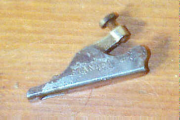
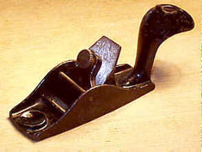
#90 Steel cased rabbet plane, 9"L, 1 1/2"W, 2 5/8lbs, 1877-1888. *
 This plane is identical
to the #80, described in an earlier posting, except that
this model has a spur
for scoring the grain before the cutter cuts the wood.
Like the #80 rabbet,
these planes are difficult to find without modification.
This plane is identical
to the #80, described in an earlier posting, except that
this model has a spur
for scoring the grain before the cutter cuts the wood.
Like the #80 rabbet,
these planes are difficult to find without modification.
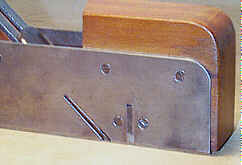
The spur is dovetailed into the right side of the
steel casing. This same
means of attachment is commonly used on the wooden rabbet
planes contemporary
with this plane. The spur is removed for sharpening or
adjusted downward by
tapping it at its top. Often, the steel casing just above
the spur will be
munged as a result of jamming a screwdriver, or similar
tool, above the spur
and twisting it. On this model, the steel casing has an
extra screw on the spur
side so that the casing won't distort around the spur.
The image here shows how the original mouth should
look. Most examples have
their mouths filed with an arch-shape opening to allow freer
passage of the
shaving. See the #80 rabbet plane for a view
of what the mouth looks like
on the other side.
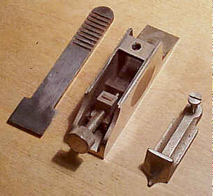
#90 Bull nose rabbet plane, 4"L, 1"W, 1lb, 1898-1969.
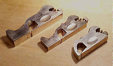 This is the first in a
series of so-called cabinetmaker's rabbet planes, and is the
rightmost one in
the image (the larger planes are pictured to show the
details of the text). They
were advertised as being "designed for fine Cabinet Work
where extreme
accuracy is required." The distinguishing feature of this
plane that sets
it apart from the others, other than its overall length, is
its very short toe
section. This section is roughly 1/4" long, which makes it
suitable for
bullnose work.
This is the first in a
series of so-called cabinetmaker's rabbet planes, and is the
rightmost one in
the image (the larger planes are pictured to show the
details of the text). They
were advertised as being "designed for fine Cabinet Work
where extreme
accuracy is required." The distinguishing feature of this
plane that sets
it apart from the others, other than its overall length, is
its very short toe
section. This section is roughly 1/4" long, which makes it
suitable for
bullnose work.
They all are cast iron, with full nickel plating. The
amount of original
nickel plating that remains on these planes has a tremendous
effect on their
value, but has absolutely no effect on their use. The sides
are ground flat
and, supposedly, square to the bottom. All the planes in the
series have the
"HAND-Y" grip feature, like that on the block planes, milled
into
their sides to allow for a more comfortable grip. They can
be used either right
or left handed.
Each plane's sole is of a two-section construction -
one section forms the
toe of the sole, and the other forms the heel of the sole.
The toe section sits
atop, and slides over, the heel section, and together they
are secured by means
of a large slotted screw. This screw is loosened to adjust
the plane's mouth by
sliding the toe section over the heel section, and then
tightening the screw.
Through repeated use, this screw can become mangled, so
check for that. Also,
check the area of the casting where this screw threads into
the heel section as
it's prone to cracking, which is impossible to see without
taking the plane
apart, and even with it apart a crack can be difficult to
detect. Check where
the screw butts against the toe section for any signs of
stress cracks that may
result from over tightening the screw.
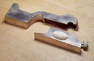 The toe section can be
removed completely from the plane so that it can be used as
a chisel plane.
Stanley, in their tool propoganda, claimed that with the
plane configured as a
chisel plane it was useful for the removal of dried glue.
There are better ways
to remove that than to use this plane. However, the plane
does function nicely
as a chisel plane and is particularly useful when working
rabbeted frames,
where the stiles and rails join. The planes are a lot less
costly than the
dedicated chisel plane that the company made, the #97.
The toe section can be
removed completely from the plane so that it can be used as
a chisel plane.
Stanley, in their tool propoganda, claimed that with the
plane configured as a
chisel plane it was useful for the removal of dried glue.
There are better ways
to remove that than to use this plane. However, the plane
does function nicely
as a chisel plane and is particularly useful when working
rabbeted frames,
where the stiles and rails join. The planes are a lot less
costly than the
dedicated chisel plane that the company made, the #97.
Inside the toe section is a little set screw,
oriented parallel to the sole,
that can be set to regulate the mouth's opening. This set
screw is only
accessible when the plane is apart. It butts up against the
larger slotted
screw used to hold the two sections together. This little
set screw is what
keeps the mouth constant, to a pre-set width, as the two
sections are screwed together.
This capability to maintain the mouth's opening is a handy
feature to have,
though it is by no means mandatory, for the times that the
toe section is
removed, either to hone the iron or to use the tool as a
chisel plane.
The set screw oftentimes is seized into the toe
casting, which is something
you won't be able to tell unless you carry along a small
screwdriver to
disassemble the plane before you buy it. If the set screw is
seized, don't try
to free it without first letting it soak with some
penetrating oil - the slot
for the screwdriver may snap off, if you're impatient,
leaving you a fine mess
to solve. If you're having trouble closing the mouth of the
tool, you have to
drive the set screw deeper into the casting since it's
preventing the toe section
sliding farther back over the heel section as the set screw
is butting against
the larger slotted screw that secures the two sections
together. Some guys just
removed the set screw from the plane since they mustn't have
liked screwing
with so many screws.
 The plane's cutter is
sorta spade-shaped (the shovel kind). It is pitched at
roughly 20 degrees, with
its two edges perpendicular to the cutting edge being
chamfered. The cutter is
as wide as the plane is over the length of the plane's bed,
where it abrubtly
diminishes to a constant width as it extends through the
plane's body, poking
out at the heel of the plane. The cutter is removed from the
plane through the
mouth whenever grinding or honing is required. The cutter is
used bevel-side
up, as is the case for most planes that have their cutters
pitched lower than
~35 degrees.
The plane's cutter is
sorta spade-shaped (the shovel kind). It is pitched at
roughly 20 degrees, with
its two edges perpendicular to the cutting edge being
chamfered. The cutter is
as wide as the plane is over the length of the plane's bed,
where it abrubtly
diminishes to a constant width as it extends through the
plane's body, poking
out at the heel of the plane. The cutter is removed from the
plane through the
mouth whenever grinding or honing is required. The cutter is
used bevel-side
up, as is the case for most planes that have their cutters
pitched lower than
~35 degrees.
A large, knurled adjusting screw protrudes from the
heel of the plane. This
screw activates a mechanism like that found on the #60's series of block planes;
i.e., the screw activates
a cast iron sliding section, which sits freely atop a
machined inclined plane.
Together, the sliding section and the inclined plane form
a sort of tongue and
groove so that the sliding section doesn't become
misaligned as it moves over
the inclined plane. The sliding section has a small nib on
it that engages
machined grooves in the cutter's backside.
The adjusting screw on the older models is larger and
somewhat cruder than
on the later models as it's a cast piece. The knurling is
coarser on the older
ones, and "STANLEY" is cast in a circle on the screw's knob.
On the
later models, it's sometimes difficult to tell whether the
plane is
American-made or English-made. The cutter, at its top, is
stamped with the plane's
origin. It's often hard to read the origin unless the plane
is taken apart. The
larger rabbet planes of this series have their country of
manufacture stamped
on the circular disk at the toe (see #92 for more about this disk) as
well as on their
cutter. The earliest models of the plane have the patent
date stamped into the
iron.
 These planes, despite
Stanley's claim that they are machined accurately, are
sometimes not so. They
were offered as premium planes in direct competition with
the products made by
Norris, et al, in England. If you are hankering to own an
affordable
better-quality rabbet plane, these Stanley products are
certainly that, but
they are no match (surprise) to the English products.
Stanley made these planes
general purpose so that they can be used as regular rabbet
planes, chisel
planes, and shoulder planes. Their cutters are pitched lower
than might be
expected for rabbeting so that they can be used as shoulder
planes. The English
designed two distinct planes for these tasks, with each
particularly suited for
the tasks. However, the English versions, despite their
functional and visual
superiority over the Stanley versions, are considered very
expensive by most in
the user community, making the Stanley products an
affordable alternative.
These planes, despite
Stanley's claim that they are machined accurately, are
sometimes not so. They
were offered as premium planes in direct competition with
the products made by
Norris, et al, in England. If you are hankering to own an
affordable
better-quality rabbet plane, these Stanley products are
certainly that, but
they are no match (surprise) to the English products.
Stanley made these planes
general purpose so that they can be used as regular rabbet
planes, chisel
planes, and shoulder planes. Their cutters are pitched lower
than might be
expected for rabbeting so that they can be used as shoulder
planes. The English
designed two distinct planes for these tasks, with each
particularly suited for
the tasks. However, the English versions, despite their
functional and visual
superiority over the Stanley versions, are considered very
expensive by most in
the user community, making the Stanley products an
affordable alternative.
When buying these planes, it's good to carry along a
small machinist's
square to test them for truth. Also, check the mouth to make
sure that it
hasn't been tampered with (like filed) and that it is a
uniform width across
its length. Make sure that it isn't chipped, especially at
the corners, as they
sometimes are, or that it shows any signs of stress
cracking. Inspect the area
where the two sections mate, along its entire length, for
this is another area
that seems to suffer stress cracks or broken chunks off the
toe section. Sight
along the plane's sole to check that the toe section is
aligned with the heel
section. I've seen far too many examples of these planes
where they are not
aligned due to sloppy machining. This problem appears to be
found more often on
the later and larger (#92, #93,
#94)
examples of these planes.
By far, the most common damage that any of these
style planes can suffer is
found on their lever caps. The lever cap is secured in place
by turning a small
slotted cap screw, with a screwdriver, which causes the
lever cap to place
pressure on a bridge that spans the inside width of the heel
section. Since the
lever caps are rather long in relation to their thickness,
it's very easy for
them to snap in two. This damage is usually unseen, unless
the plane is
completely taken apart. Often, the break is welded and
ground flat. The repair,
if done well, has no effect on the plane's use, but a
collector will head for
the hills should one be waved under his nose.
All the above applies to each of these rabbet planes,
up to the #94 inclusive.
This model of the plane was the most popular in the
series, as judged by its
long production, and was the first in the series to be
offered by Stanley. It
seems as though Stanley was testing the waters before they
took the plunge to
make the longer planes. The first model of this plane
doesn't have its number
embossed anywhere on it, but eventually the number was
embossed at the top,
toward the toe. A copy of the plane, and its two larger
brothers, is still made
in England.
#90A Cabinet makers' rabbet plane, 4"L, 1"W, 1lb, 1937-1943. *
Just when I go and say all the above applies to
everything that follows,
Stanley decides to offer this little oddball. It's basically
the same plane as
the #90,
except that it's different (hohoho!). Hell, one might
assume that this one is
aluminum, if one followed Stanley's numbering scheme. But
no, this one ain't
aluminum. It appears that Stanley had enough sense to
never introduce that
metal to this style of plane.
What sets this plane apart from the #90 is that its body is a
one-piece construction. It is
a bullnose rabbet plane, but there is no provision to
adjust its mouth (like
the two section #90). It has a similar, but
different, blade adjusting
mechanism - a knurled nut engages a single slot in the
cutter, which is a
cheaper mechanism than that provided on the #90. The knurled nut travels over
a 1 3/8" long
threaded rod, which itself is threaded into the main
casting, at the heel of
the plane. The nut is stamped "No. 90A". The cutter has
"90A" stamped into it, but more importantly, it has "MADE
IN
USA" also stamped into it, which is very important, if
you're a collector
willing to shell out the $1000+ it takes to own this guy.
The lever cap isn't captive to the plane; you can remove it
completely from the
plane, which must be done to remove the iron. The lever cap
has a small locking
wheel beneath the area where you rest your palm. This wheel,
when turned,
places pressure directly below on the iron, and forces the
lever cap upward
against the main casting (this style of lever cap is common
on the English-made
rabbet and shoulder planes). The lever cap has "STANLEY"
embossed in
the palm area, and "MADE IN USA" down where it rests above
the honed
edge of the cutter. Again, "MADE IN USA" is mandatory for
this to be
a proper and complete USofA product. Check that the lever
cap hasn't been
brazed, cracked, or chipped. Be sure to look where the
locking wheel threads
into the lever cap's casting for any signs of damage.
Lastly, check that the
lever cap's little 'peak', where it engages the main
casting, isn't chipped or
broken.
These planes were never popular over here, and the
war helped to speed its
death. As a result, they are very rare. Afterall, why would
someone purchase a
non-adjustable rabbet plane, when the#90 offered the same
function, but with more bells and
whistles? Certainly not too many would, which accounts for
its scarcity. Even
the glitzy nickel plating of the thing couldn't boost
sales.
#90J Cabinet makers' rabbet plane, 4"L, 1"W, 1lb, 1937-1943. *
This plane is identical to the #90A, except with two differences. There is no blade adjusting mechanism other than the dexterity of your hands. The plane's top is japanned, with its sides polished. The Stanley English version of this plane is identical to this one, but it doesn't have the Made in USA logo on it. This, and the #90A are tough monkeys to find, but only of the USofA manufacture.
#91
No #91. Why Stanley didn't assign the #90A to this number we'll never know. Heck, they probably didn't know either. Heh, heh, heh, those guys in charge of number designation at Stanley sure were a riot!
#92 Cabinet makers' rabbet plane, 5 1/2"L, 3/4"W (1"W, 1962 on), 1 1/2lbs, 1902-1969.
 Goto #90, read that, and
apply these dimensions to get a feel what this plane is.
Goto #90, read that, and
apply these dimensions to get a feel what this plane is.
But wait, there's a bit more to be said about this
plane, the #93, and the #94, which cannot be
said of the #90. These longer planes have toe sections that are
much longer than the
small bull nose toe section of the #90. Consequently, there was a
tendency for these toe
sections to become misaligned with the heel section over
time due to the
internal stresses inherant to cast iron.
The earlier models of these larger planes have solid
toe sections. The later
models, ca. WWI onward, each have a circular disk that's
recessed and affixed
to the toe section. You don't want to go popping this disk
off to find out
what's behind it, but if you did, you'd find a hollowed out
toe section, filled
with a metal cylinder to give the plane its weight. By
hollowing out the toe
section, Stanley was able to overcome the risk of the toe
section warping in
relation to the heel section. This treatment was no
guarantee that the two sections
were aligned; sloppy machining would defeat that purpose.
The disk has the
company logo on it, and that logo reflects the one in vogue
during the time the
plane was manufactured.
The circular disk was dropped from the later examples
of these planes, and
the current English models don't have the disk. It's
probable that the cost of
manufacturing these planes with the disk became too
expensive so the planes
were made like they were when first offered - a solid toe
section, with no
disk.
The very first models of this plane, and its two
larger brothers that
follow, do not have the number cast into them. They also
have a composite toe
section where a portion of the front sole is cast separately
and then pinned to
the rest of the casting. This method of manufacture must
have been very costly
to produce, never mind the requirement of extreme accuracy.
Stanley probably
did this to help eliminate any movement of the toe section
long after that
casting was machined. The amount of mass of a solid toe
section could warp or
distort just a fraction, throwing the machined accuracy of
the toe section
relative to the heel section out of truth.
The mating edges of the toe section to the heel
section is also different on
the earliest model of these larger planes. They are machined
to form a broad
arch and thus only make contact with the heel section on 4
small edges, 2 on
each side. This method of mating the two castings was easier
to machine as
there was less area on the toe section that had to be true,
however the resulting
strength of this method didn't prove strong enough to hold
up during use, and
the method was dropped soon after it was tried.
Some of the planes can be found without the
strengthening cross rib that
spans the opening where the palm rests on the tool. The
model number, cast into
the flat length of the toe section, can be found oriented
relative to the heel
or the toe of the plane (the numbers are upside down to each
other when
comparing different models of the planes).
#93 Cabinet makers' rabbet plane, 6 1/2"L, 1"W, 1 3/4lbs, 1902-1964.
Goto #92, read that, and apply these dimensions to get a feel what this plane is.
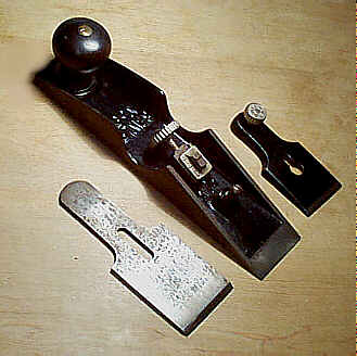
#94 Cabinet makers' rabbet plane, 7 1/2"L, 1 1/4"W, 2lbs, 1902-1943. *
Goto
#93, read that, and
apply these dimensions to get a feel what this plane is.
This is the one plane
of the series that approximates the role of the heavier
and larger English
infill shoulder planes, and is a good alternative to those
expensive planes,
when this plane is found in its typical used condition.
Given this, it's no surprise that many of these planes are
found over in England, American buyers never fancied this
model.
This plane is the most difficult to find of the
series, and it's doubly
difficult to find in crispy, nickely new condition.
Furthermore, because of the
extra length of mating surfaces between the toe section and
heel section, the
machined area where the two meet can often be found cracked
or with chunks of
the toe section broken out. The planes also seem to suffer
cracks where the toe
section arches down to meet the heel section more often than
its smaller brothers
do. Check this area very carefully as cracks in this area
can be very difficult
to detect.
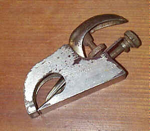
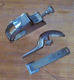
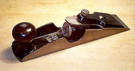
#95 Edge trimming block plane, 6"L, 1 1/16"W, 1 1/4lbs, 1911-1961.
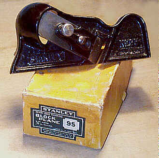 This is another very
useful plane, which a well-equipped shop should have. It's
not an inexpensive
plane, but it's worth every cent you pay for it. Several
modern manufacturers
have made copies of this plane out of a glistening bronze
alloy, which can
oxidize and leave marks on your work just like the
forgetable aluminum bench
planes that Stanley dumped on happy planers of yesteryear.
One maker of these
planes supplies them in left and right hand versions. The
original only comes
in a right hand version.
This is another very
useful plane, which a well-equipped shop should have. It's
not an inexpensive
plane, but it's worth every cent you pay for it. Several
modern manufacturers
have made copies of this plane out of a glistening bronze
alloy, which can
oxidize and leave marks on your work just like the
forgetable aluminum bench
planes that Stanley dumped on happy planers of yesteryear.
One maker of these
planes supplies them in left and right hand versions. The
original only comes
in a right hand version.
The plane has a V-shaped sole that forms a right
angle. One leg of the V
carries the cutter, which is set at a skew, and the other
leg acts as a fence.
A small lever engages grooves machined in the back of the
cutter so that it can
be set by lifting or lowering the lever. Check that this
mechanism works well
and that the lever engages the cutter securely.
A screw-activated lever cap holds the cutter in
place. Sometimes, the screw
was cut a bit short, making it difficult or impossible for
the lever cap to
hold the iron in place securely. If the lever cap screw
'bottoms out' and the
iron's adjustment lever can be moved easily, the cutter will
not stay in place
during use. You can sometimes remedy the problem by
tightening the slotted
screw which the the lever cap engages.
Since the plane's sole is machined so that it forms a
right angle, the plane
is used to true up edges. It works equally well against the
grain or along the
grain. With a very fine set to the cutter, and a very keen
edge on the cutter,
the plane does very well on end-grain. A lot of guys like to
use this plane to
square up the edge after they've jointed it. While you can
do that, it's better
to learn to joint properly, and save this short soled plane
for other tasks.
The portion of the sole that's perpendicular to the
iron has two holes - one
at the toe and one at the heel - drilled in it so that you
can secure a
bevelled piece of wood on the sole to make it cut off of 90
degrees. This is
useful for bevelling edges. Just be sure to orient the wood
piece so that the
narrowest portion is toward the iron otherwise you can't
make effective use of
the relatively narrow width of the cutter.
The earliest model of the plane has the Stanley logo
in script to the lower
left of the cutter. On the back of the main casting can be
found the patent
date, "U.S.PAT.5.14.12", embossed above the sole.
Check that there are no chips or cracks on the main
casting and that the
lever cap hasn't been snapped in two and repaired. I've seen
a few of these
planes that have a hairline crack in the arched portion of
the casting just
behind the cutter.
In the wasteland of stupid planes Stanley ever
produced, this is surely one
that can't be categorized that way.
#96 Chisel gauge, 2 1/4"L, 3/8"W, 1/12lbs (yup, one over twelve pounds), 1888-1922. *
 This is not a plane per
se, but it does function like one. What it is is a tiny
little gauge, which
sorta looks like a plane, that is fixed to a chisel to allow
blind nailing.
Blind nailing is where a shaving is partially lifted from
the wood's surface, a
nail is driven under the shaving's position, and the shaving
finally glued back
in place. The maximum width chisel the tool can accept is
1/4".
This is not a plane per
se, but it does function like one. What it is is a tiny
little gauge, which
sorta looks like a plane, that is fixed to a chisel to allow
blind nailing.
Blind nailing is where a shaving is partially lifted from
the wood's surface, a
nail is driven under the shaving's position, and the shaving
finally glued back
in place. The maximum width chisel the tool can accept is
1/4".
A captive lever cap, made of nickel plated cast iron,
fastens the gauge to
the chisel; a slotted screw actives the lever cap. The tool
is made of nickel
plated steel. Check that the sole is flat, and that it
hasn't been ground
convex as it's possible to find some examples that have been
so modified.
It's kind of a stupid tool, since a chisel alone, in
a skilled hand, can
accomplish the same thing. They are scarce little tools,
easily overlooked when
scrounging for old stuff. And definitely stay away from
those that are brass or
aren't nickel plated as the tool is being reproduced by
modern toolmakers. The
originals will have "STANLEY" stamped into the left cheek,
and the
earlier one will have the patent date, "PAT AP'L 10-88"
stamped into
the right cheek.
#97 Cabinet makers' edge plane, 10"L, 2 1/4"W, 3 3/4lbs, 1905-1943. *
 This plane sorta looks
like a wedge with a turned rosewood knob at its rear. The
knob, always a low
style, is identical to those used on the evil #6, and it sits atop a raised
ring in the casting to
help reduce the likelihood of its chipping about its base.
The knob is secured
to the plane with the common threaded post and nut, but
the nut is nickel
plated, unlike the nut used on the common bench planes.
This plane sorta looks
like a wedge with a turned rosewood knob at its rear. The
knob, always a low
style, is identical to those used on the evil #6, and it sits atop a raised
ring in the casting to
help reduce the likelihood of its chipping about its base.
The knob is secured
to the plane with the common threaded post and nut, but
the nut is nickel
plated, unlike the nut used on the common bench planes.
There is no mouth on this plane - it has no bearing
surface ahead of the
cutter making the plane really nothing but a chisel held at
a constant pitch
and regulated by the sole to prevent it from digging into
the wood too deeply.
The plane carries a cutter that is as wide as the
plane is with it bedded
bevel side up. The cutter is pitched at about 20 degrees,
and it rests on the
sides of the bottom casting, which are machined to form an
inclined plane. If
you were to use this plane, and forget its value as a
collectible, you'd want
to make sure that the machining was true with both sides in
the same plane. The
entire length of the backside of the cutter does not rest on
the side rails;
only the leading edge of the cutter makes direct contact
with the side rails
and the bed proper.
The cutter is held in place by a thumb
screw-activated lever cap that is
entirely japanned. The cutter is adjusted by the familiar
screw mechanism found
on the common block planes. The sides of the plane each have
a U-shaped cutout
on them to allow better access to the adjusting screw. The
sides are also
machined at right angles to the sole.
 The plane was marketed
to piano makers in particular and cabinetmakers in general.
It was designed to
cleanup or trim inside work, where the space is limited and
the use of any
other plane is impossible. Obviously, this a very special
purpose plane for
rare occurences in the shop.
The plane was marketed
to piano makers in particular and cabinetmakers in general.
It was designed to
cleanup or trim inside work, where the space is limited and
the use of any
other plane is impossible. Obviously, this a very special
purpose plane for
rare occurences in the shop.
Like the #62, these planes have a tendency for chipping at the
leading edge of the
bottom casting, directly below the cutter, due to the
thinness of the casting
there. The left and right corners of the leading edge on
some examples of these
planes are not finished at a right angle, but are instead
slightly angled in an
attempt to reduce chipping.
Chipping doesn't harm the plane's use, as long as the
chipping isn't too
severe, but it really kills the plane's value to your
average Stanley collector.
If yours is chipped, and you can't sell it to a collector,
you can always use
it as a doorstop - its wedge-shape makes it perfect for that
role.
Check that the tool hasn't been reworked, where an
example, with a minor
chip, was machined to eliminate the defects. Sight down the
machined side
rails, on which the cutter rests, to make sure they are
straight and true. Any
deviance from a straight edge on these means that a portion
of the side rails
has been machined so that the leading edge can be cut back a
bit to eliminate
the chip. The underside of the cutter clears the back end of
the machined side
rails by about 1/16"; if it's less than that amount, chances
are that the
plane was chipped and remachined. One of the tell-tale signs
of a re-work is the
machining marks at the very end of the casting, where the
chipping occurs;
original machining leaves curved milling marks concentric
with each other a la
the layers of an onion. The marks are very fine, but they
are there.
The earlier castings, down along the U-shaped
'cut-outs' of the side rails,
do not have the quarter-sphere bumps that the later castings
do. These 'bumps'
were likely added to the casting to give it strength and to
make the pattern
pop free of the sand easier during the casting of the tool.
#98 Side rabbet plane, 4"L, 1/2"W, 1/2lb, 1896-1942.
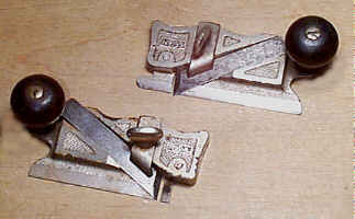 This is a small and
rather flat plane with a narrow cutter secured diagonally
across the plane's
main casting. Behind the cutter is a small, turned, rosewood
knob. The cutter
is secured with a sorta J-shaped clamping mechanism, which
is tightened with a
thumb screw (check that this thumb screw isn't stripped, as
many of them are).
The plane has a very narrow "sole," which is more like the
runners,
or skates, on a #45 than it is a sole (in the bench plane sense). The
backside of the
plane is machined flat.
This is a small and
rather flat plane with a narrow cutter secured diagonally
across the plane's
main casting. Behind the cutter is a small, turned, rosewood
knob. The cutter
is secured with a sorta J-shaped clamping mechanism, which
is tightened with a
thumb screw (check that this thumb screw isn't stripped, as
many of them are).
The plane has a very narrow "sole," which is more like the
runners,
or skates, on a #45 than it is a sole (in the bench plane sense). The
backside of the
plane is machined flat.
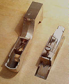
The front portion of the skate is reversible so the
plane can be worked in a
bull nose fashion, as shown in the lower example in the
photograph. This
portion is secured to the main casting with a small
countersunk screw. Make
sure that the bull nose section hasn't been snapped off from
misuse. Curiously,
many of the planes are broken, and repaired on the main
casting where the
portion that carries the knob widens to meet the rest of the
casting. Like the #79, this
plane, and the #99, can suffer cracking to the casting along the
milled bed of the
cutter. See the #79's listing for that
information.
The plane is used to cleanup the sides of rabbets,
dadoes, grooves what have
you. Like the #79, the cutters on this plane are far too narrow for
me, so I, instead,
have a wooden pair, where I can utilize their capability
to make larger cuts.
That, and the fact that these are very small planes which
I find difficult to
grasp comfortably. However, unlike wooden side rabbets,
which tend to have
wider soles than this plane, the #98 & #99 can undercut sides better, like when doing the
housing for a sliding
dovetail. The other knock against wooden side rabbets is
that they can, and
often do, warp over their length. This plane does not
suffer that flaw.
This plane is referred to as the right one of the
pair, which means it is
pushed from left to right with its knob facing your body.
This is kinda weird,
seeing how it is opposite the way a conventional plane is
pushed - from left to
right - when this plane is said to be for righthanded use.
The plane was introduced prior to the #99, its mate, to see how well it
would be received by
the public. Apparently, it went well for the planes aren't
all that rare. The
earliest models have the patent date stamped into the
skate. Starting around
1930, the plane came equipped with an adjustable depth
stop located on the
backside. The depth stop is secured to the plane with a
small thumb screw, and
the backside of the plane has a vertical V-groove cut into
it to accept a
tongue-like surface on the depth stop. This mating of the
depth stop and main
casting is identical to that used on the #78, and similar planes, and helps
to keep the depth
stop laterally stable so the sole of the stop is parallel
to the surface being
worked.
One may wonder why to go with this plane and its
brother over the #79, which
rolls the functions of both planes into a single tool. On
the plus side, the #79 is easily
half the cost of the #98 and #99 combined, as might
be expected since two planes should be twice the cost of
one, right? The best
reason to go with the pair of planes over the #79 is that
you can always leave the irons set in the pair, whereas
you have to back off
the 'trailing' iron of the #79, if you want to follow good
planing practice.
Dragging an iron backward over wood can dull or injure it.
Some folks will take the knob off the plane and use
it on a #1 that's in
need of knob (the #1 is more valuable than the #98, so it's sacrificed for the
cause). The knob is
held to the plane using the common threaded rod and
slotted nut, but the nut on
this plane is nickel plated. The blade clamp is
interchangeable with the #79.
#99 Side rabbet plane, 4"L, 1/2"W, 1/2lb, 1897-1942.
This plane is the left one of the pair - it is pushed from right to left. It is identical to the #98, except that it is the mirror image of that plane. These planes are found less frequently than the #98's are. The plane is the topmost one pictured under the #98's description.
#100 Block plane, 3 1/2"L, 1"W, 3/8lb, 1898-1958.
 Never thought I'd make it
to #100, did you?
Well, neither did I.
Sad thing is, I've got another 100, or so, to go. UGH!
What a thankless task
this is. I wish I had listened to my father's advice to
become a professional
wrestler, er, where was I? Oh yeah, this is a toy-sized
block plane, designed
to be used with one hand. It has a squirrel tail iron
handle at its rear, which
rests nicely in the palm of the hand. The handle has a
hole drilled in it so
that the tool can be hung out of the way.
Never thought I'd make it
to #100, did you?
Well, neither did I.
Sad thing is, I've got another 100, or so, to go. UGH!
What a thankless task
this is. I wish I had listened to my father's advice to
become a professional
wrestler, er, where was I? Oh yeah, this is a toy-sized
block plane, designed
to be used with one hand. It has a squirrel tail iron
handle at its rear, which
rests nicely in the palm of the hand. The handle has a
hole drilled in it so
that the tool can be hung out of the way.
The plane is particularly suited for miniature and
model work. A simple
screw-activated lever cap, which is forced against a rod
that extends across
the plane's width (cheek to cheek), is used to secure the
cutter in place. This
same method of securing the cutter is common to other planes
that follow. There
is no cutter adjustment mechanism; this is done entirely by
hand.
Later models, ca. post-WWII, have their lever caps
finished in red paint which
gives them a unique look from the ones that are all
japanned. Many of the
planes have no markings on them, including the cutter.
[ START ] |
[ PREV ] | [ NEXT
] | [ END ]
[ HOME
]
Copyright
(c) 1998-2012 by Patrick A. Leach. All Rights Reserved.
No part may be
reproduced by any means without the express written
permission of the author.