The Superior Works: Patrick's Blood and Gore Planes #100 1/2 - #140
Quick Find: #100 1/2, #101, #101 1/2, #102, #103, #104, #105, #110, #112, #113, #118, #120, #122, #127, #129, #130, #131, #132, #135, #140
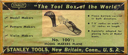
#100 1/2 Block plane, 3 1/2"L, 1"W, 3/8lb, 1936-1962.
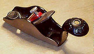 This little plane is
identical to the #100, with its squirrel tail
handle, but differs in that
its sole is convex both toe to heel (12" radius) and side
to side
(7/8" radius). The plane was advertised as being useful
for model and
pattern makers.
This little plane is
identical to the #100, with its squirrel tail
handle, but differs in that
its sole is convex both toe to heel (12" radius) and side
to side
(7/8" radius). The plane was advertised as being useful
for model and
pattern makers.
 Like the #100 and the #101, the lever cap was
painted red from 1941 through final production. The main
casting is japanned,
with the exterior machined.
Like the #100 and the #101, the lever cap was
painted red from 1941 through final production. The main
casting is japanned,
with the exterior machined.
This plane, as well as the #100 and #101, has a small, circular
depression, in which to
place your index finger during use, at the toe. It also
has a hole drilled in
its handle so that it can be hung on a nail.
Stanley actively solicited ideas from tradesman, and
others, for tools that
they could make. This plane is an example of one such plane,
and in an early
Stanley advertisement for the plane, they specifically
mention this fact:
|
This
modelmaker's convex plane fills Like many other
modelmakers, |
#101 Block plane, 3 1/2"L, 1"W, 1/4lb, 1877-1962.
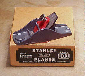 Same style of plane as
the #100
and #100 1/2. However, this plane has no rear handle like the
two previous. The
plane was designed for household use, and lighter work. It
was originally sold
in toy tool chests, but gained such popularity that it was
soon advertised as a
craftsman's tool.
Same style of plane as
the #100
and #100 1/2. However, this plane has no rear handle like the
two previous. The
plane was designed for household use, and lighter work. It
was originally sold
in toy tool chests, but gained such popularity that it was
soon advertised as a
craftsman's tool.
The earliest model of the plane has the top of its
cutter rounded in a
slight arc from side to side. The later model has the top of
its cutter
finished in an angular fashion, like those of the common
bench planes. Many of
these planes have been modified by users to do custom tasks,
with the most
common modification being its conversion to a bull nose
function, similar to
the #101 1/2.
This plane is japanned over its entire main casting,
except for the sole.
The lever cap is also japanned, but starting around 1941 it
was painted red.
The last models of the plane are painted grey and have a red
lever cap, and
very much resemble the Millers Falls' version of the plane.
Many manufacturers made knock-offs of this plane,
with Sargent&Co.
having cranked out a load of them under their model number
104, which is
usually found cast into the tool right behind the cutter.
Another company even
made an aluminum version of this tool, probably trying to
cash-in on Stanley's
incrediblely successful aluminum plane products. Er, on
second thought,
probably not.
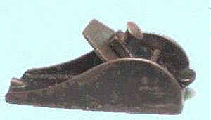
#101 1/2, Block plane, 3 1/2"L, 1"W, 1/4lb, 1881-1928. *
 This is a very scarce
plane, which was never offered in any of Stanley's tool
catalogs, but was
offered in the catalogs of the major tool dealers in the
United States and
England. In fact, it's in England where most of these little
guys are found.
This is a very scarce
plane, which was never offered in any of Stanley's tool
catalogs, but was
offered in the catalogs of the major tool dealers in the
United States and
England. In fact, it's in England where most of these little
guys are found.
The plane is nothing but a bull nose version of the #101, with one very important
difference - there is a
small finger rest cast into the bridging member of the
casting that spans the
width of the plane, forward of the cutter, giving the
plane the appearance of
Fudgy the Whale sticking his tongue out, when viewed from
the side. This is
very important to remember, if you are a collector, since
the scum of the human
gene pool will grind the front of the #101 off, and try to pass it off as
an original example.
Would have been a nice try, except that the plane doesn't
measure up to the
length of a true #101 1/2.
#102 Block plane, 5 1/2"L, 1 1/4"W (1 3/8", 1914 on (1 5/16, 1962), 7/8lb, 1877-1962.
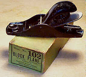 This is a cheap (both
price and construction) block plane, with no adjustment
mechanism. A
featureless cutter sits over a raised, inclined projection
of the bottom
casting. A rod spans the side of the plane, under which a
lever cap is secured.
The lever cap has a large metal wheel on its underside,
which, when turned,
puts downward pressure on the cutter, directly below it. The
casting that
receives this wheel, underneath the lever cap, is sometimes
broken. If it is,
don't worry, this is a common and cheap enough tool that you
can find another.
But, I think they are junk, so why not trash it or give it
to your dog as a
chew toy, instead?
This is a cheap (both
price and construction) block plane, with no adjustment
mechanism. A
featureless cutter sits over a raised, inclined projection
of the bottom
casting. A rod spans the side of the plane, under which a
lever cap is secured.
The lever cap has a large metal wheel on its underside,
which, when turned,
puts downward pressure on the cutter, directly below it. The
casting that
receives this wheel, underneath the lever cap, is sometimes
broken. If it is,
don't worry, this is a common and cheap enough tool that you
can find another.
But, I think they are junk, so why not trash it or give it
to your dog as a
chew toy, instead?
There is no front knob, but there is a nice circular
depression in which you
can place your index finger during use. The plane is
japanned over the entire
main casting, except for the sole. Later examples of the
tool can be found with
a grey paint on the lever caps.
The first model of the plane has a solid lever cap,
whereas the later model
has an opening in the area where it engages the rod. Who
cares? They're both
junk.
#103 Block plane, 5 1/2"L, 1 1/4"W, (1 3/8", 1914 on), 7/8lb, 1877-1950.
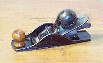 This is the same plane
as the #102, but
it has a cheesy lever adjustment mechanism. This mechanism
is held captive in
the raised projection mentioned in the #102 description. The lever grips
grooves machined into
the underside of the cutter. Like the #102, a circular depression is cast
into the toe of the
plane to provide a finger rest. The iron is pitched at 20
degrees.
This is the same plane
as the #102, but
it has a cheesy lever adjustment mechanism. This mechanism
is held captive in
the raised projection mentioned in the #102 description. The lever grips
grooves machined into
the underside of the cutter. Like the #102, a circular depression is cast
into the toe of the
plane to provide a finger rest. The iron is pitched at 20
degrees.
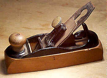
The first model of this plane, illustrated here, is a
bit different - it has
a turned, wooden (fruitwood) front knob that screws onto a
thread boss of the
main casting. The knob is often replaced, missing, or split.
It has
"103" cast into the plane, not embossed (raised numbers), at
the
heel. The iron has the company name stamped in an arch at
the heel of the iron,
and directly below that is the 1876 patent date. This model
of the plane is
rather scarce and is collectible, but it's still a piece of
junk when compared
to the better block planes, equipped with all the bells and
whistles.
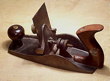
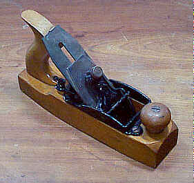
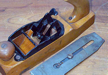
#104 Smooth plane, 9"L, 2 1/8"W, 3 1/8lbs, 1877-1918.
This is the first in a series (interrupted though it is) of cheaper bench planes, which were aimed at manual training and home handymen. This, and the #105, have steel bottoms, while the others in the series have wooden bottom. The steel bottom design is much thinner than the cast Bailey bottoms. Thus, they are lighter in weight than the corresponding sizes of the Baileys. One of the later catalog references to them states that the planes are practically unbreakable and that they are particularly useful for outdoor and rough work.
The bottoms are a composite construction. There is a
U-shaped main portion,
which corresponds to the main casting of a cast iron Bailey,
onto which are
rivetted a piece forward of the mouth, to carry the knob,
and piece behind the
mouth, to carry the 'frog' and the tote. The piece behind
the mouth has four
projections aranged in a square. The two projections nearest
the mouth are
shorter than those farthest from the mouth. Both are
'bevelled' so that they
can receive the backside of the iron. These projections are
cast iron and are
not adjustable; if any of them are cracks or broken, you're
pretty much S.O.L.
trying to fix them unless you're good at welding. Between
the projections and
running to the heel of the plane is a hump on the rivetted
piece. Rosewood is
used for the tote and knob, and the tote on this plane is
unique in that it has
a concave bottom to fit over the aforementioned hump.
The unmistakable lever cap has a Liberty Bell, with
the number
"76", cast into it. The reason why, is left as an exercise
for the
reader. The planes are often referred to as "Liberty Bells"
by the
tool collecting boys. Again, the reason why is left as an
exercise for the
reader.
The lever cap is of the common cheaper style, where
it's activated by a
thumb screw and sits under a rod, peened into the cheeks of
the plane. The
lever cap screw is cast with heavy knurling about it. The
screw is sometimes
japanned and sometimes nickel plated (it's more often
japanned), with the lever
cap entirely japanned.
The cutter is adjustable for depth by means of a
two-pronged lever held
captive between the projections that the iron rests upon. On
the business end
of the lever is a pin-like projection, which engages a
depression in the bottom
of the cap screw. Thus, this plane's cap screw is different
from that of the
Bailey design, so you should check that it's proper. The
screw is much smaller
than the Bailey's, and has a noticeable depression on the
slotted side. There
is no lateral adjustment mechanism.
Check that the cap iron is original. Since the tool
has its own cheaper
mechanism for adjusting the set, it also has its own cap
iron, which isn't
slotted like it is for the Bailey patent planes.
The planes are very rugged, and there is little that
can go wrong with them,
from a design standpoint. However, most of them suffered
harsh treatment, and
show it, usually with cracked totes and pitted soles. Check
the adjustment
lever, and its linkages, for breakage.
#105 Jack plane, 14"L, 2 1/8"W, 3 7/8lbs, 1877-1918.
Same as the #104, except that it is a jack size plane.
#110 Block plane, 7 1/2"L (7", 1917 on), 1 3/4"W (1 5/8", 1909 on), 1 3/8lbs, 1876-1973.
 This was a very popular
block plane. It is like the #102, except it's longer. But, it's
still a cheap piece
of junk when compared to Stanley's other block planes.
There is no adjustment
mechanism provided on the plane, and proper irons have
backsides that are
without any notches; i.e. they are featureless and flat.
This was a very popular
block plane. It is like the #102, except it's longer. But, it's
still a cheap piece
of junk when compared to Stanley's other block planes.
There is no adjustment
mechanism provided on the plane, and proper irons have
backsides that are
without any notches; i.e. they are featureless and flat.
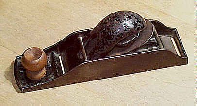
The first and second model, pictured here, of the
plane are vary scarce and
collectible. These two models have a fancy, floral cast
lever cap, which sort
of resembles a shoe-buckle. A small lever cap wheel
(four-pronged and cast of
brass on the first model, knurled and cast of iron on the
later models)
activates the lever cap. The lever cap is held captive by
the rod, which screws
into the left check of the plane. Since the cap is so
delicate, it is often
found broken either where it pivots on the rod or back where
the tightening
wheel threads into it.
By the early 1880's, the plane took on a more
conventional appearance,
losing its Victorian look. Because the of the lever cap's
fragility it was no
longer held captive to the plane, and lost its intricate
design save for a six
or five pointed star cast into it until the early 1890's.
The lever cap from
then on was featureless, making a dull plane even duller.
Sometimes, the later
lever cap is so badly damaged that the tightening wheel can
no longer place
sufficient pressure on the iron to keep it set. Thus, it's
possible to find
these planes with crude repairs and ingenious means to hold
the iron in place,
with one of the most common being the removal of the lever
cap altogether in
favor of a simple wooden wedge that's driven under the cross
rod. Seems kinda
retro, recalling the days of old when wooden wedges held
irons in place, but it
actually works.
The front knob is often replaced on the earliest
models, since it is friction
fit inside a raised boss in the bottom casting. Many guys
solved the problem of
the knob falling out by drilling a hole through the main
casting and then
securing the knob with a screw. The first model of the plane
is the rarest of
all types, and has a distinct boat-shape to it. It's a nice
looking plane,
albeit very fragile - the aforementioned breakage to the
lever cap is most
common, followed by cracks in the cheeks and about the
mouth.
The problem of the front knob falling out of the
plane was solved by
screwing it directly onto a raised thread boss cast into the
main casting.
Planes with this feature have rosewood knobs until after
WWII, at which time
they became stained hardwood.
Because the plane has no adjustment features, other
than your setting the
iron by hand, the iron's backside is flat. Any holes or
grooves in the backside
mean it's a replacement. The iron can often be found
mushroomed at the top due
to its being set by a hammer in a manner like wooden planes
are set.
Be sure to check where the lever cap's tightening
screw threads into the
lever cap for any sign of crack in the tapped boss. Also,
check the lever cap
about the area where it rests under the rod (that spans the
side of the plane)
for any signs of cracks; on the later models this part of
the lever cap is
somewhat fragile due to the void cast in the lever cap.
#112 Scraper plane, 9"L, 3"W (2 7/8", 1925 on), 4lbs, 1885-1944.
 In the humble (hah!)
opinion of the author, this is one of the finest tools ever
to have been
unleashed on the public from New Britain, Connecticut. For
the longest time,
the plane labored in relative obscurity among a cult of
those adroit in the
fine points of scraping. It used to be that these things sat
unloved at tool
events and auctions, and one almost ducked for cover when
asking $75 for one.
However, a popular scratch n' sniff magazine prominently
featured the plane on
the cover of an issue, and the prices of the things have
never been the same.
Everybody wants one, and once you use one, you'll see why.
Hey, my life isn't
complete without one, and I gotta have one - press here to order.
In the humble (hah!)
opinion of the author, this is one of the finest tools ever
to have been
unleashed on the public from New Britain, Connecticut. For
the longest time,
the plane labored in relative obscurity among a cult of
those adroit in the
fine points of scraping. It used to be that these things sat
unloved at tool
events and auctions, and one almost ducked for cover when
asking $75 for one.
However, a popular scratch n' sniff magazine prominently
featured the plane on
the cover of an issue, and the prices of the things have
never been the same.
Everybody wants one, and once you use one, you'll see why.
Hey, my life isn't
complete without one, and I gotta have one - press here to order.
The tool is nothing but the #12 configured like a #4 smoothing
plane. It has the typical rosewood knob and tote like
those found on the Bailey
bench planes, and it is gripped and pushed just like the
bench planes are.
Optional cutters could be purchased to turn the plane into
a toothing plane;
the toothing cutters were available in 22, 28, and 32
teeth per inch. These
same cutters also fit the #12.
The earliest model has a bead at the bottom of its
front knob. The blades on
these first models have the top edge beveled at both
corners, probably to spare
the workman's hand/knuckles/fingers should his grip ever
slip and slam into the
blade (this same blade can also be found on the earlier #12's). These
blades are not common at all, and they were probably soon
dropped in favor of
ones with a straight edge along both short dimensions
(across the width) of the
blade for the reason that some folks like to have both
ends of the blade with a
burr to be at the ready when one edge goes dull.
The earliest models do not have the number cast into
them. They also have
the patent date (8/31/58) stamped into the brass adjusting
nut closest to the
tote. The astute reader will note that the patent date on
the nut is nearly
some 30 years earlier than the supposed year this plane was
introduced. Since
the patents expired by the time this plane was offered in
the catalog, it seems
odd that Stanley would put this nut on the #112. Perhaps they were doing it to intimidate would
be copiers, ignorant
of patent law, as a warning, but it's more likely that
they were just using up
old stock since the same nut can be found on the #12's produced
during this time. It may be possible that Stanley produced
the plane prior to
1885, perhaps 10 years earlier (catalogs and production
dates were many times
out of synchronization) while the patent was still
applicable.
Look at the spewage for the #12 for things that can be damaged
on this plane. In
addition, check the area of casting, from the sole, where
the handle rests.
There is a rather fragile extension to the main casting
here, which sometimes
can be found broken. Never buy one with a high knob of the
style found on the
bench planes - they only came with the low knob (although
some models have a
taller than usual low knob that's unique to this plane).
Strangely, many of the earlier planes (say up to WWI)
have an unusually thin
coat of japanning, making it common for the planes to be
found with their finish
peeling or blistering. Maybe someone in the #112 department was taking home bottles of
japanning to paint the town
black?
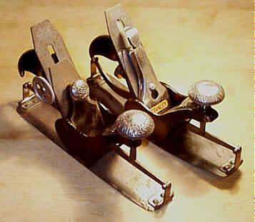
#113 Circular plane, 10"L (10 1/4", 1936 on), 1 3/4"W, 3 1/2lbs, 1879-1942.
 You would think that the
two other Stanley circular planes would have satisfied
Stanley, but no, they
had to come up with another design. This one probably arose
from the need to
compete with Leonard Bailey's better Victor design, the #20, where the
adjustment of the front and rear portion of the sole
occurred in unison via a
single adjusting knob.
You would think that the
two other Stanley circular planes would have satisfied
Stanley, but no, they
had to come up with another design. This one probably arose
from the need to
compete with Leonard Bailey's better Victor design, the #20, where the
adjustment of the front and rear portion of the sole
occurred in unison via a
single adjusting knob.
This plane has the typical thin steel sole attached
to the main casting by
dovetailed keys (the earliest design) or screws (later
design to solve the
problem of the sole breaking free). A large, mushroom-shaped
knob, located on
the front of the plane, adjusts the flexible sole by raising
a screw that is
attached to the forward pivoting arm. This arm is connected
to a gear, located
on the left of the main casting, which, in turn, drives
another gear that is
connected to the rear arm. Thus, both portions of the sole
are adjusted
simultanously. Later models have graduations machined into
the gears to help
set the plane to a particular curvature.
The earliest models of the plane have a japanned
lever cap with a fancy
nickel plated screw. The lever cap sits into two slots on
either side of it.
Depth adjustment of the cutter is done by a side wheel (on
the right) that
activates a clever sliding section that's machined into the
bed. The front knob
is also decoratively cast and nickel plated; it's embossed
"STANLEY RULE
AND LEVEL CO." in a circular fashion, with "PATENTED
SEPTEMBER 25,
1877" inside the previous embossing, followed by a Greek key
pattern
inside the patent date. Both the front and rear arms are
straight. There is no
lateral adjustment mechansim.
Later planes have the typical Bailey style
adjustments. The plane's main
casting was redesigned to accomodate the full features of
the bench plane
design - the brass depth adjustment screw, the lateral
adjustment lever, and
the slotted lever cap. The rear arm of the plane is curved,
whereas the front
arm is straight, just like the earlier models.
There is a scarce later variant of this plane, where
it has the full Bailey
patented features as well as a highly decorative nickel
plated front knob. This
knob has a four-lobed decoration cast into it, and was often
used on the planes
that Stanley made under contract for hardware firms such as
Keen Kutter.
 Check the linkages on
the
sole for any signs of stress tears. Also check the area
where the sole is
dovetailed to the main casting for any cracks. Make sure the
grip for the rear
hand (behind the cutter) is present and secured tightly -
many of these planes
have had their grip screws stripped off or are missing the
grip altogether.
Check the linkages on
the
sole for any signs of stress tears. Also check the area
where the sole is
dovetailed to the main casting for any cracks. Make sure the
grip for the rear
hand (behind the cutter) is present and secured tightly -
many of these planes
have had their grip screws stripped off or are missing the
grip altogether.
Also check the slots in the main casting where the
old style lever cap
engages the main casting - this area is prone to chipping
and cracking. For
working purposes, make sure the sole adjusting screw isn't
stripped (adjust the
sole through its entire range) and that the cutter depth
adjustment wheel moves
the plate up and down freely (remove the iron to inspect
it). Check under the
front knob for any signs of repair to it, where it fits onto
the threaded rod
that raises/lowers the front arm. While inspecting this
area, check the main
casting itself, right behind the adjuster, since some of the
planes break here
and are welded back together.
Adjust the iron up and down with it in the plane. The
cap irons are unique
to this plane, and they can be found with cap irons taken
from a standard #3. The slot in
the cap iron is located higher up on the compass planes
than it is on the bench
planes. If a #3 cap iron is used on this
plane, it's impossible to
get a satisfactory set on the iron.
I don't really like this plane for the reason that
its sole can go out of
set during use. The same knob that's used to adjust the sole
is also used to
grip during planing. So, it's easy to change the adjustment
of the sole.
Stanley recognized this problem, and provided the later
planes with a set screw
that tightens the knob after the sole has been set. This
screw sits just
forward of the knob and is received by the main casting,
which is split so that
it can pinch the knob. The earliest models do not have this
screw. Despite my
dislike of the plane, others didn't - it's probably (in my
experience) the most
numerous of the four compass planes that Stanley sold, the #13, #20, #20 1/2, and #113.
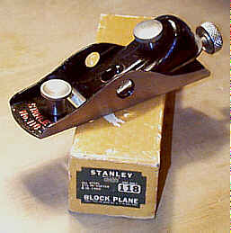
#118 Block plane, 6"L, 1 5/8"W, 1 1/4lbs, 1933-1973.
 I love this plane, not
because it's a good one to use, but because of its
description in the catalogs
- it was advertised as being "boy proof."
I love this plane, not
because it's a good one to use, but because of its
description in the catalogs
- it was advertised as being "boy proof."
The plane was designed for use in manual training and
rough work. It has a
pressed steel bottom, and has only three separate parts to
it - the cap, the
bottom, and the cutter. All screws are captive to the plane.
There are two circular cutouts, one on each side of
the plane, that are a
cheap substitute for the Hand-y grip, which is found on the
better block
planes.
The plane is finished with a thin black paint, which
often is found peeling.
The embossing at the toe, both "STANLEY" and "No. 118", of
the plane can sometimes be found with orange or red paint to
highlight it. The
exterior is machined, and the screws are nickel plated.
Later examples will
have the identifying marks stamped into the left side of the
plane. The later
models will also have a gray colored finished to the lever
cap.
The cutter is pitched at 12 degrees, and is
adjustable by an end screw.
There is no adjustable mouth on this plane. This plane is
also a piece of junk
when compared to the other low angle block planes, but some
might find it
useful to strip paint.
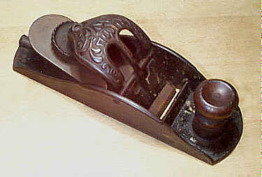
#120 Block plane, 7 1/2"L (7", 1917 on), 1 3/4"W (1 5/8", 1909 on), 1 3/8lbs, 1876-1950.
 Like the #110, but with an
adjuster like that found on the #103. It's a piece of junk. Use it
as a clay pigeon, or
something like that, but only if it isn't the earliest
model, which is a very
scarce tool.
Like the #110, but with an
adjuster like that found on the #103. It's a piece of junk. Use it
as a clay pigeon, or
something like that, but only if it isn't the earliest
model, which is a very
scarce tool.
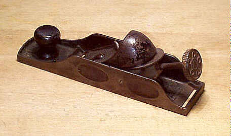
The first model, pictured here, is characterized by a
5-point star embossed
on the lever cap, and is one of Stanley's scarcest block
planes. It also has a
turned applewood knob that slips into a cast socket. The
next model used a
similar knob, but it's threaded onto a cast boss, and the
lever cap has the
common 6-point star. The later models have a smooth lever
cap, and are
interchangable with the cheezier #110. In what must have been an
attempt to make crap
shine, Stanley eventually provided a rosewood knob on this
thing and finally
settled upon a stained hardwood knob near the end of the
plane's life.
The adjustment mechanism on the first model is
identical to that used on the
Liberty Bell planes. The earliest #120
iron has a slot cut in it, much like that found on the
bench planes, through
which a slotted screw passes. The bottom of the screw
engages the adjustment
mechanism, whereas the top is fastened with a nut. As the
iron is used, the nut
and screw are moved 'up' the slot in order to take
advantage of the adjusters
range. The cutter has the patent date of "Pat. April 18.
1876"
stamped into it.
Soon after the debut of this plane, the adjustment
mechanism was changed
probably because it proved to be too complex for such a
cheap plane. The back
of the iron used on the later models has a series of grooves
milled in it to
engage a simpler adusting lever. This lever is pinned to two
raised bosses on
the main casting, and they should be checked for cracks, if
you're considering
buying this cheap tool.
#122 Smooth plane, 8"L, 1 3/4"W, 2 3/8lbs, 1877-1917.
 This plane has the same
lever cap and adjusting mechanism as that found on the #104 and #105 (see the #135 for its larger brother
exposed). It is a wood
bottom version of this style of cheap plane. It has no
tote, but, instead, has
a raised portion of the casting to fit into the palm.
Sometimes, this portion
is broken, and the rest of the casting, which is screwed
to the wooden body,
can sometimes crack so you should examine it carefully.
This plane has the same
lever cap and adjusting mechanism as that found on the #104 and #105 (see the #135 for its larger brother
exposed). It is a wood
bottom version of this style of cheap plane. It has no
tote, but, instead, has
a raised portion of the casting to fit into the palm.
Sometimes, this portion
is broken, and the rest of the casting, which is screwed
to the wooden body,
can sometimes crack so you should examine it carefully.
The iron rests upon two vertical and triangular
(almost fin-like in
appearance) projections of the main casting. Between these
two projections is
housed the linkages that permit the iron to be adjusted. The
lowermost part of
the adjusting mechanism is grooved to receive the tab that's
secured to the cap
iron. Check this grooved portion of the adjusting mechanism
to make sure that
it isn't broken - it can sometimes be found snapped
rendering the adjuster
useless.
Since the plane is fairly short, and the casting
crowds the area where the
adjusting mechanism is, the two-pronged lever that's common
to the larger
planes of the series is replaced with a lever that has a
finger loop. The lever
is cast iron and it, too, can snap or crack, so check it out
before buying.
The sole and the knob are beech, as is all the wood
on the rest of this
series. Most of these planes, and their larger brothers, are
found in dogmeat
condition and have very little appeal to collectors/users,
but antique shops
don't realize this since most of them are priced way more
than they are worth
as firewood.
The lever caps for these wooden Liberty Bells are not
interchangable with
their two metallic brothers; the wooden models use longer
lever caps than the
metallic ones use. Also, you can't snarf parts from a Bailey
style bench plane,
be it wooden or metallic, as all the parts, save for the
iron, are unique to
this series of plane.
#127 Jack plane, 15"L, 2 1/8"W, 3 1/2lbs, 1877-1918.
Longer plane than the #122, but with a tote. It also has the pronged adjustment lever since there is room enough for it.
#129 Fore plane, 20"L, 2 3/8"W, 5 5/8lbs, 1877-1918.
Like the #127, only longer.
#130 Double end block plane, 8"L, 1 3/4"W (1 5/8", 1909 on), 1 5/8lbs, 1884-1955.
 This is the cheaper model
of the two block planes that have two cutter seats, where
the cutter can be
turned end for end to make the plane either work regular or
bull nose. On the
regular end of the plane is a turned wooden knob (hardwood,
on earlier models,
and rosewood on the later models), which threads directly
upon a threaded boss
that arises from the main casting. Check that the knob
proper isn't stripped.
The plane does not have the common "Hand-y" feature found on
most of
Stanley's block planes.
This is the cheaper model
of the two block planes that have two cutter seats, where
the cutter can be
turned end for end to make the plane either work regular or
bull nose. On the
regular end of the plane is a turned wooden knob (hardwood,
on earlier models,
and rosewood on the later models), which threads directly
upon a threaded boss
that arises from the main casting. Check that the knob
proper isn't stripped.
The plane does not have the common "Hand-y" feature found on
most of
Stanley's block planes.
The first model of the plane has a star cast into the
lever cap, and the
side rails of its main casting are more arched over their
lengths. The casting
was soon redesigned so that each of the side rails have a
noticeable flat
length, with two curved portions meeting the flat length.
The proper irons on
these earlier models will have the plane's patent date
stamped in it -
"PAT'D JAN.30.82" with "REIS'D OCT.23.83" immediately
below. Later models of the plane have the typical logos that
are found on other
planes/tools. Since the plane hasn't any adjustment
mechanism, the backside of
the iron is flat; never buy one of these planes with a
grooves milled into it
backside, if you're collecting.
There are two rods that span the sides of the plane,
which engage the
typical lever cap with the large wheel underneath. The plane
looks like the #110, but with a bull
nose end to it. Adjustment of the cutter is done manually.
The cutter rests
upon two triangular and fin-like projections that rise
from the main casting.
At the 'apex' of these projections is a semicircular shape
where the iron makes
contact. Check that these projections aren't cracked. The
early planes will also
have the patent date cast (incised) between the two
projections; "PAT.
OCT. 23. 83" in fine, barely legible characters.
Check the casting on the bull nose end of the plane
for any cracks or signs
of repair. Some guys would roll their own #97 by grinding off the bull
nose end of the plane to
lay the cutter bare in order for it to function like a
chisel plane.
#131 Double end block plane, 8"L, 1 3/4"W (1 5/8", 1909 on), 1 1/2lbs, 1905-1941. *
 This is the same basic
plane as the #130,
except that it has the depth adjustment mechanism and same
style of lever cap
as found on the #60 series of block planes. It
also has the Hand-Y
feature, two on each side, milled for gripping; four
Hand-Y grips are obviously
better than just two. This is a fairly tough plane to
find, especially free of
damage.
This is the same basic
plane as the #130,
except that it has the depth adjustment mechanism and same
style of lever cap
as found on the #60 series of block planes. It
also has the Hand-Y
feature, two on each side, milled for gripping; four
Hand-Y grips are obviously
better than just two. This is a fairly tough plane to
find, especially free of
damage.
A clever modification to the depth adjusting screw is
the cool idea behind
this tool. Imagine your basic depth adjusting screw, like
that on the #118 (it's a few planes
before this one's description), that can pivot down at its
bottom so that the
adjusting knob can be flipped from end-to-end relative to
the plane's sole. If
you can think of that, then you can see how that sort of
adjuster can benefit
this plane since it has two mouths. However, for this
adjustment to be
beneficial, it needs to engage the back of the cutter when
the cutter is in
either position. Thus, the sliding portion of the adjuster
has two machined
faces on it, both of which have a small nib to engage the
cutter, and its these
faces that slip into their corresponding pair of inclined
bosses that arise
from the main casting. A perfect solution for two-position
adjustability, or so
one would think, but there are problems with it.
The sliding portion of the adjuster is cast from
iron, and is rather thin
where it mates with the inclined bosses. It also can spin
about the adjusting
screw when it's not seated. The problem here, then, is that
the sliding portion
can be cocked just enough so that when you flip the
adjuster, the edge of the
sliding portion slams into the non-machined area of the
bosses causing the
sliding portion to crack and chip. This is a very common
form a damage found on
these planes.
 Furthermore, because
the
bottom of the adjuster is a fulcrum point, the main casting
can crack or chip
where the adjuster pivots. The adjusting yoke (which itself
is secured to the
main casting with two screw, each driven from the side of
the plane) also can
crack about its pivotting point. This area of the plane
needs very close
inspection.
Furthermore, because
the
bottom of the adjuster is a fulcrum point, the main casting
can crack or chip
where the adjuster pivots. The adjusting yoke (which itself
is secured to the
main casting with two screw, each driven from the side of
the plane) also can
crack about its pivotting point. This area of the plane
needs very close
inspection.
The plane does not have a lateral adjustment lever;
the would have been an
impossibility for Stanley to pull-off without making the
plane too complex. The
lever cap screw (the one that engages the lever cap to act
as a fulcrum point)
is repositioned in the main casting to the respective mouth
position; i.e.
there is only one lever cap screw on the plane. Were there
two lever cap
screws, the adjuster couldn't slide over a suitable range.
The plane has a rosewood knob that threads directly
onto the main casting.
The plane is japanned with its exterior machined. The
adjuster, the sliding
section, and the yoke are all nickel plated. The plane is
embossed with its
model number behind the knob. The first model of the plane
has the patent dates
embossed on the main casting (note that it also has a wider
cutter). If you
need a cutter for the plane, any common 1 5/8" wide block
plane cutter,
with machined grooves in the back, will work. As with the #130, check the casting about
the bull nose mouth for
any signs of cracks or repairs.
#132 Jointer plane, 26"L, 2 5/8"W, 7 3/8lbs, 1877-1918.
Like the #129, only longer.
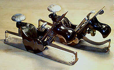
#135 Smooth plane, 10"L, 2 1/8"W, 3lbs, 1877-1918.
|
|
|
Like the #122,
but with a tote and a two-pronged lever. The rear portion
of the plane is
stepped in a razee-fashion, like the #35 is designed.
If you look closely at the iron in the rightmost
image, you'll notice a slot
in the cap iron, below the cap iron's screw. In this slot is
a little steel
piece that engages the groove in the adjusting mechanism to
raise and lower the
iron. This little piece has a tongue milled on it and is
held to the cap iron
with a six-sided nut that's mounted on the opposite side of
the cap iron.
Note that the casting that carries the adjusting
mechanism is different than
that used on the #35; this casting is shorter
in length and doesn't
follow the razee (curved rearward area of the stock)
section to carry the tote.
Instead, the tote is simply screwed to the beech stock and
has an additional
screw at the toe of the tote.
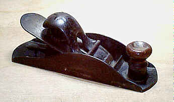
#140 Rabbet and block plane, 7"L, 1 3/4"W (1 5/8", 1936 on), 1 1/8lbs, 1896-1944.
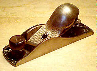 This is a very useful
plane, and is one of Stanley's better products (it would
have been even better
if they didn't supply it with the cheesy lever cap wheel
like that found on the
#110, et al, and
if it had an adjustable mouth). The plane can be used to
trim crossgrain
rabbets, the cheeks of tenons, for cutting rabbets,
general block plane work,
etc. The plane's number is embossed on its heel.
This is a very useful
plane, and is one of Stanley's better products (it would
have been even better
if they didn't supply it with the cheesy lever cap wheel
like that found on the
#110, et al, and
if it had an adjustable mouth). The plane can be used to
trim crossgrain
rabbets, the cheeks of tenons, for cutting rabbets,
general block plane work,
etc. The plane's number is embossed on its heel.
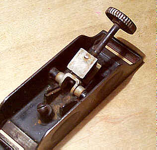
The right side of the plane has a removable plate,
and is secured in place
by two slotted screws. With the plate on, the plane
functions as a regular
block plane. With the plate off, the plane becomes a rabbet
plane (the cutter's
right edge coincides with the rightmost edge of the sole).
The earlier side
plates have the patent date stamped into them. You can
sometimes find a huge
burr on either the front and/or rear edge of the side plate.
This burr results
from grinding the side plate attached to the main casting
during manufacturing.
You may want to file the thing off (but only if the plane is
a user and not a
collector) since you can draw blood from it if you're not
careful.
Also on the right side of the plane, on its
sole (this would be the
left side of the plane when you flip it over and look at
it), can often be
found a
high or low spot at the back of the mouth. This area results
from movement in
the main casting after it was machined, where the sole
can twist over its
length. The only portion of the plane that can possibly lend
assistance in
keeping the sole flat, the right cheek of the casting, isn't
sufficient to keep
the sole ahead of the iron and sole behind the iron
co-planar. The twisting
resulted either from a casting that wasn't allowed to season
sufficiently prior
to machining or from just sloppy machining by a New Britain
Joe Timeclock what
was nursing a hangover or something. When you note this
'problem', it's
certainly one plane that can benefit from the lapping craze
that has the free
planing world firmly in its grip.
A flat lever adjustment mechanism, like that provided
on the cheap #120 plane, is found on
the first model of these planes, but it was soon replaced
with the depth
adjusting screw that's found on the #60 series of block planes. The
lever adjuster just
doesn't hold the cutter firmly in place like the knob
adjuster does. The cutter
is pitched at 20 degrees with its cutting edge ground to a
slight skew, which
makes it cut across the grain better. The cutters used on
both models of the
tool have a series of fine grooves pressed into the
backside of the iron. These
grooves engage a corresponding piece of the adjuster to
grip the cutter firmly.
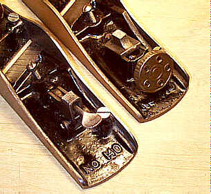 Like any of the block
planes with the depth adjustment screw, be sure to check
that the threads of
the screw are not stripped. If the plane has a cast
adjustment knob, like the
one to the right in the photograph, check that it hasn't
been snapped off and
then brazed back onto the threaded rod.
Like any of the block
planes with the depth adjustment screw, be sure to check
that the threads of
the screw are not stripped. If the plane has a cast
adjustment knob, like the
one to the right in the photograph, check that it hasn't
been snapped off and
then brazed back onto the threaded rod.
Give the plane a good inspection on its left side in
case there are any
cracks or repairs. When the side plate is off the plane, the
left side of the
plane, just to the left of the mouth, is the only area that
is keeping the
plane's main casting in one piece.
The plane is often found missing its side plate -
these plates all reside in
the same realm as lost slitting cutters, cam rests, fences
for #289, etc. If
the side plate is present, don't jump for joy until after
you've checked the
screws that secure it to the plane. One or both of these
screws are often
missing or replaced. Missing screws should be rather
obvious to notice, but
replaced ones aren't. Original screws have a flat head,
often with vertical (in
relation to the shaft) knurling. They aren't brass, as
many replacement ones
are. The lever cap screw is also often replaced, for some
strange reason. This
screw is unique among the block planes, but you can snarf
a replacement from a
common #78.
A small, rosewood knob is threaded directly onto the
main casting to act as
a finger rest. This knob is often split or stripped. If so,
the same rosewood
knob from the common block planes, like the #110 or #120, can be used as a replacement.
The lever cap, fully nickel plated, is unique to this
plane, so be cautious
of replacements. A proper lever cap has a noticeable arch on
its right side, so
that it functions as part of the plane's side when the side
plate is removed.
The cutter is also unique to the plane; it has parallel
sides, which become
narrower about 1/3 back from the cutting edge, with the heel
of the iron
rounded. Make sure that a common block plane iron has not
been substituted in
the plane.
[ START ] |
[ PREV ] | [ NEXT
] | [ END ]
[ HOME
]
Copyright
(c) 1998-2012 by Patrick A. Leach. All Rights Reserved.
No part may be
reproduced by any means without the express written
permission of the author.