The Superior Works: Patrick's Blood and Gore Planes #201 - #444
Quick Find: #201, #203, #205, #212, #220, #238, #239, #239 1/2, #248, #248A, #271, #278, #282, #283, #289, #292, #340, #378, #444
Hah, just when you thought all of Stanley's plane
guts were strewn about the
information superhypeway, along comes some more road pizza.
This time, there
are some bloody sights to behold....
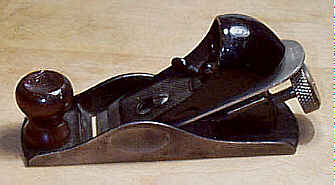
#201 Block plane, 3 1/2"L, 1"W, 1/4lb, 1906. *
This plane is identical to the #101, the toy-size block plane, except for its finish. This one is nickel plated, whereas the #101 is japanned. Collector alert - watch for re-plated #101's passed off as real #201's.
#203 Block plane, 5 1/2"L, 1 3/8"W, 1 1/8lbs, 1912-1962.
 A smaller block plane
designed primarily for manual training use. The plane is
somewhat scarce due to
its size and lack of bells and whistles. The same problems
one can find on the
common block planes, like chipped/cracked mouths, stripped
adjusters, cracks in
the lever cap, etc., can also be found on this plane,
especially on those that
were on the receiving end of junior's abuse.
A smaller block plane
designed primarily for manual training use. The plane is
somewhat scarce due to
its size and lack of bells and whistles. The same problems
one can find on the
common block planes, like chipped/cracked mouths, stripped
adjusters, cracks in
the lever cap, etc., can also be found on this plane,
especially on those that
were on the receiving end of junior's abuse.
This plane has its cutter pitched at 20 degrees, and
has a cutter adjustment
mechanism like that found on the #60, et al, although the sliding
part of the adjuster
is not the same as that used on the low angle block planes
but is like those
used on the #220. The plane might be mistaken for the first model
of the #60 (those
without adjustable mouths) were it not for the pitch of
the cutter and the fact
that "203" is usually cast below the cutter's adjustment
knob.
There is no provision for mouth adjustment; i.e., the
sole is one piece. The
front knob is turned rosewood (on the earlier planes) or
hardwood (on the later
planes). The knob threads onto a threaded boss, and should
you be in need of
one, you can snag one off a #110, #120, #140 (although the tool police
might put you up against
a wall and ask why you would want to take a knob off a
more valuable plane to
put on a cheaper one), and #220, et al.
Although this is a nice, functional plane, you may
choose to leave this
plane for the kiddies, and get a larger one for the mature
and muscular you.
#205 Block plane, 6 1/4"L, 1 3/8"W, ~1lb, 1927-1934.
This is a piece of junk that only a collector, when overtaken by a fit of momentary insanity, would ever dare own. Forget it as a user tool, since it's garbage. It was offered in a boy's tool set, but never as a separate plane, in Stanley's catalogs. It was offered separately in other catalogs (hardware firms), which ought to indicate that even Stanley was embarassed with this ugly baby.
The plane is pressed steel, and has a projecting
steel palm grip which is
fastened to the bottom. A cheesy cutter securing mechanism
is nothing but a
screw through a slotted hole in the cutter. The cutter is
marked
"DEFIANCE", which says to me, whenever I see this plane, "I
defy
you to buy me." Stay away from it, it's quicksand! Heck,
it's not even
worthy as a projectile when you're looking for something to
throw at your
neighborhood's stray cats.
#212 Scraper plane, 5 1/2"L, 1 3/8"W, 1 1/2lbs, 1911-1934. *
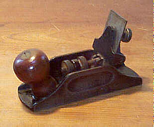 A very small scraper
designed for very small work, with very small sales, all of
which make it quite
rare. It's sorta the #1 of scrapers. It has the exact
same blade adjustment
mechanism as that found on its larger siblings, the #12 and #112 which
ultimately inspired its design, only this one has a scaled
down version.
Instrument makers (Stanley specifically mentioned violin
makers in their
propaganda), flyrod makers, etc., were the people who may
have found this plane
useful.
A very small scraper
designed for very small work, with very small sales, all of
which make it quite
rare. It's sorta the #1 of scrapers. It has the exact
same blade adjustment
mechanism as that found on its larger siblings, the #12 and #112 which
ultimately inspired its design, only this one has a scaled
down version.
Instrument makers (Stanley specifically mentioned violin
makers in their
propaganda), flyrod makers, etc., were the people who may
have found this plane
useful.
It has a turned knob, made of rosewood, similar to
that found on a common
bench plane. There are some scarcer models that have a knob
turned of mahogany.
These knobs tend to be a bit more elongated than the
rosewood version,
something you can't tell unless you've seen both. The knob
is mounted at the
rear of the casting, sitting atop an inclined boss of the
casting, and is
oriented so that it leans backward to give the workman a
better grip - it fills
the palm of his hand. The knob is attached with the common
two-piece rod and
brass nut.
The tool has the Hand-y feature milled into the sides
just like that found
on the block planes, but the milling is longer than that
done on the block
planes. I've seen an example where the sides were chopped
down to below the
Hand-y grip for some unfathomable reason.
The 'frog' (blade clamping assembly) is attached to
the main casting via a
slotted screw that's been machined flush with the sides of
the tool. The
pivoting section of the frog uses a similar screw to attach
it to its corresponding
part. Check the casting of the pivoting section, where the
screw passes through
it, for any sign of cracks or repairs. Also check where the
threaded rod joins
the 'frog' for signs of damage.
This plane has been reproduced two times. The first
time in an attempt to
fool the collectors. It's a poor job, and isn't nearly as
good as the #1's
reproduction. The second reproduction is not done in an
attempt to deceive
anyone, but is done as a modern working tool. This latter
reproduction is cast
of manganese bronze, which even the untrained eye can spot
as the
distinguishing feature from an original.
These planes are very difficult to find with their
blades marked with any
Stanley logo. Consider yourself lucky if you have one. The
model number is
embossed at the toe, under STANLEY that's cast in a
'scrolled' fashion. The
lever cap screw is non-plated brass and has STANLEY RULE
& LEVEL Co. NEW
BRITAIN, CONN USA" stamped into it in fine lettering.
#220 Block plane, 7 1/2"L (7"L, 1917 on), 1 3/4"W (1 5/8"W, 1909 on), 1 1/2lbs, 1898-1973.
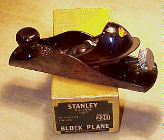 This plane is identical
to the #203,
except that it is larger. A more useful plane than the #203, but it's nice to
have an adjustable mouth, which this one, too, lacks.
Weren't those guys at
Stanley considerate by offering us such a selection of
block planes? On the
plus side, the plane is at least suitable for parts
snarfing - the rosewood
knob is identical to the one provided on the more useful,
and valuable, #140.
This plane is identical
to the #203,
except that it is larger. A more useful plane than the #203, but it's nice to
have an adjustable mouth, which this one, too, lacks.
Weren't those guys at
Stanley considerate by offering us such a selection of
block planes? On the
plus side, the plane is at least suitable for parts
snarfing - the rosewood
knob is identical to the one provided on the more useful,
and valuable, #140.
The plane is also very similar to the #120, but this one has the screw
adjusting mechanism and
sliding cutter seat that are used liberally on the low
angle block planes of
the #60 series. The lever cap is interchangeable with all
the adjustable block
planes that have the same width iron, like the #9 1/2, which
also have the lever cap screw. The earlier examples will
have the nickeled cast
iron adjusting screw; the one in the image is the common
steel one with the
crosshatched knurling and incised with "STANLEY".
The example pictured here has the original decal on
the lever cap, which was
used during the late 1920's to the early 1930's on many of
Stanley's planes.
Planes and tools in this condition should be collected and
not used; this plane
is easy enough to find in dogmeat usable condition, so
there's no need to go
ruining a mint example of what's otherwise a bland tool.
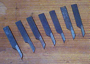
#238 Weatherstrip plow plane, 7 1/2"L (9 1/2"L, 1936 on), various widths, 1 7/8lbs, 1930-1938. *
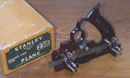 This is a plane that
none of us will ever likely use. It was designed to cut the
grooves in window
sash for the installation of weatherstripping. It really is
an ugly little
monster, and is characterized by a circular hole in the main
casting, which
accepts your first finger when gripping the plane. There's
plenty of room for
all four fingers to wrap around the tote, and it seems
strange that Stanley
provided this circular hole for finger comfort. Anyone out
there have a
surviving relative who once labored in the weatherstripping
trade what won't
mind your checking their meathooks?
This is a plane that
none of us will ever likely use. It was designed to cut the
grooves in window
sash for the installation of weatherstripping. It really is
an ugly little
monster, and is characterized by a circular hole in the main
casting, which
accepts your first finger when gripping the plane. There's
plenty of room for
all four fingers to wrap around the tote, and it seems
strange that Stanley
provided this circular hole for finger comfort. Anyone out
there have a
surviving relative who once labored in the weatherstripping
trade what won't
mind your checking their meathooks?
A tiny depth stop is positioned just forward of the
cutter - it measures
just 7/8" long. Seven cutters were provided with this plane
- 1/8",
5/32", 3/16", 7/32", 1/4", 5/16", and 3/8". These
cutters sorta look like the cutters a machinist uses in a
lathe. The right edge
of the cutter aligns with the right side of the skate.
If the plane's design, and function, aren't weird
enough for you, certainly
you'll find the means to secure the cutter to be among the
weirdest of any
Stanley plane. Two large slotted screws 'sandwich' the
widest portion of the
cutter. These screws are milled so that they have a smaller
diameter below the
head. The head of each screw bears down upon the cutter -
one screw forward of
the cutter, and one behind the cutter - driving the cutter
against the machined
area in the main casting. These screws each rest in a
semicircular depression
of the main casting, and these areas can suffer chipping and
cracking. Seems as
though someone at Stanley had a real bad plane design day on
this one.
 The plane
carries what appears to be 4 arms, two pair of one large and
one small. There
is actually one pair of arms, each of which screw into the
main casting, and
it's on these arms that the fence is secured with smallish
nickel plated thumb
screws. Ahead of each arm is a smaller diameter rod that's
held in position
with a slotted and flat-headed screw. Both of these smaller
rods are actually
stops that allow the weatherstripping dude to make repeat
cuts when the fence
is moved; the rods slam up against the main casting to
prevent the fence from
being moved closer to the cutter. These rods are often
missing from the plane,
and unless you can figure out a good use for them, you won't
miss them if yours
doesn't have them. Sometimes, the stops are replaced (by
guys trying to make a
bland plane more attractive so that they can get them off
their table). Each
stop has a groove milled toward its end with a piece of wire
bent around and
into the groove to increase the diameter of the stop, making
it difficult for
it to slip out of the fence. Stanley must have foreseen the
likelihood of these
stops entering the same realm as cam rests, slitting
cutters, core box
turnbuckles, etc.
The plane
carries what appears to be 4 arms, two pair of one large and
one small. There
is actually one pair of arms, each of which screw into the
main casting, and
it's on these arms that the fence is secured with smallish
nickel plated thumb
screws. Ahead of each arm is a smaller diameter rod that's
held in position
with a slotted and flat-headed screw. Both of these smaller
rods are actually
stops that allow the weatherstripping dude to make repeat
cuts when the fence
is moved; the rods slam up against the main casting to
prevent the fence from
being moved closer to the cutter. These rods are often
missing from the plane,
and unless you can figure out a good use for them, you won't
miss them if yours
doesn't have them. Sometimes, the stops are replaced (by
guys trying to make a
bland plane more attractive so that they can get them off
their table). Each
stop has a groove milled toward its end with a piece of wire
bent around and
into the groove to increase the diameter of the stop, making
it difficult for
it to slip out of the fence. Stanley must have foreseen the
likelihood of these
stops entering the same realm as cam rests, slitting
cutters, core box
turnbuckles, etc.
The fence on this plane is as long as the plane
itself is. Make sure that
the portion of the fence in front of the front arm and the
portion behind the
rear arm are present and not broken. There are two holes
drilled in the face of
the fence for attaching an auxiliary fence.
The original cardboard boxes for this plane are
unusually 'spacious' when
compared to the tight fits provided on the boxes' of other
planes. Stanley made
this one deep enough so that the plane could be stored
assembled. Why? Good
question. Maybe they touted the roomy box as a cool feature
of the plane. Then
again, maybe not.
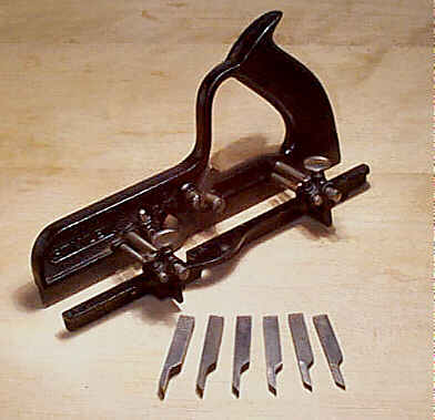
#239 Special dado plane, 7 1/2"L, various widths, 1lb (1 1/2lbs with fence), 1915-1943. *
You ready for this one? This ugly little thing, very much resembling the #238, was used for blind wire grooving, which was a fad sweeping across America. I'm sure electricians far and wide slugged it out, tooth and nail, to be the first on the block to own one. The plumbers of America surely musta felt slighted that they didn't have a plane to call their own.
This was a plane that underwent many transformations
during its too long
existence on this planet. The earliest models look just like
the #238, but without a
fence. Since some thrill seeking electrician was using the
plane across grain,
and word of that got back to Stanley, a vertical spur was
added to the plane so
that the wood would be scored before the cutter did its
cutter thing.
Electricians musta rejoiced over their clean blind wire
dados. Oh to have been
a fly on the wall at that time! Finally, a fence was added
to the plane ca.
1925 to make the plane function more like a regular
plough. Shame on Stanley
for thinking that they could pass off a crappy little
plane on the electricians
and believing that they wouldn't know any better! It took
them electricians a
little time to figure what was going on, but they finally
got what shoulda been
theirs from the get go.
The plane came in four different widths, sized by the
cutters: 1/8",
5/32", 3/16",1/4".
#239 1/2 Special dado plane, 7 1/2"L, 1/8"W, 1 1/2lbs, 1919-1923. *
Special in the sense that this is the same plane as the #239, but had a fence. The plane was dropped once some Stanley Einstein realized that the #239 should have had a fence from the start. The plane was only offered in one width - 1/8".
This is a very difficult plane to find, but only the
collectors, who have to
have one of every plane Stanley ever made, care about it.
#248 Plow plane, 9 1/2"L, various widths, 2 1/4lbs, 1936-1943.
Another in a series of forgettable planes, which shoulda never been made. This one was designed to cut grooves for weatherstripping and light ploughing. It sorta looks like the #238, except this one is elongated, doesn't have the circular opening in the casting. It has a depth stop. Only two cutters were provided with the plane - 1/8" and 5/32". Just another piece of flotsam adrift in Stanley's sea of shame.
#248A Plow plane, 9 1/2"L, various widths, 2 1/4lbs, 1939-1958.
 Stanley offered this
plane as one of their ill-fated weatherstripping tools, and
it replaced the
defunct #238
while retaining the cutter securing screws used on that
dead and buried plane.
This marvel of technological advancement notwithstanding,
the plane is as
unimaginative in design as that velvet Elvis painting that
you found at a local
starving artist sale and now have hanging over your
mirrored waterbed.
Stanley offered this
plane as one of their ill-fated weatherstripping tools, and
it replaced the
defunct #238
while retaining the cutter securing screws used on that
dead and buried plane.
This marvel of technological advancement notwithstanding,
the plane is as
unimaginative in design as that velvet Elvis painting that
you found at a local
starving artist sale and now have hanging over your
mirrored waterbed.
Lucky for us Stanley didn't put the letter "A" in
front of the
number, or we woulda been stuck with the aluminum version of
the #248 (as if the mere
existence of the #248 isn't enough to suffer). Nope,
in this case, the
letter "A", as a suffix, indicates that this plane was
another mutant
of a plane that coulda been made/offered as one complete
model. The plane does
not have the letter "A" cast into it.
What's the distinguishing characteristic (from the #248) of this genetic dead end?
Nothing but the addition
of 5 cutters - 3/16", the ever popular 7/32", 1/4", 5/16",
and 3/8". The cutters (as well as the depth stop and the
stop and fence
screws) are interchangeable with those of the #238. The stops of this plane have
a different treatment
to them than the #238 does. Each stop has two little
integral burr-like
projections near the end to keep from sliding out of the
fence.
The plane is limited in the depth it can cut - up to
5/8" deep. If you
plan to use this thing, and a lot of guys like to use this
goober for lightduty
ploughing, you should check that the skate and/or the fence
aren't chipped;
both the skate and fence are the same length. The fence has
two holes drilled
into it to allow a wooden face to be attached. The plane has
a rather strange
casting for the integral handle - a web-like portion can be
found at the bottom
of each side of the handle. This area of the casting can be
found cracked or
chipped.
#271 Router plane, 3"L, 1/4"W, 3/8lb, 1926-1973.
 A handy, small router
for light work. It's one of Stanley's better ideas, which
gained favor from
those doing inlay, mounting small door hardware, etc. The
plane is a flat,
rectangular casting, with a vertical portion at the midpoint
that is used as a
grip and to secure the cutter (by means of a simple slotted
screw). There are
two positions on which the cutter can be attached to the main
casting. One
position allows the tool to be used for normal work, and the
other position for
bull nose work.
A handy, small router
for light work. It's one of Stanley's better ideas, which
gained favor from
those doing inlay, mounting small door hardware, etc. The
plane is a flat,
rectangular casting, with a vertical portion at the midpoint
that is used as a
grip and to secure the cutter (by means of a simple slotted
screw). There are
two positions on which the cutter can be attached to the main
casting. One
position allows the tool to be used for normal work, and the
other position for
bull nose work.
Some guys would mount a block of wood on the tool by
tapping holes through
the casting (in the vertical portion, where you grip the
tool), and then screw
the wood to the casting. This after-market option was done so
that a better
grip could be had on the tool.
The plane is nickel plated, and is still manufactured over
in England. A
short production of japanned models was offered during WWII.
These are very
scarce, but no one, as yet, cares.
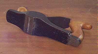
#278 Rabbet and filletster plane, 6 3/4"L, 1"W, 2lbs, 1915-1943. *
 This is a dual-purpose
plane - the primary function is to cut rabbets and the other
is to confound you
over how the blessed thing is gripped without contorting
your fingers in
directions they aren't supposed to go. Ergonomics wasn't
invented yet to help
this thing be user-friendly.
This is a dual-purpose
plane - the primary function is to cut rabbets and the other
is to confound you
over how the blessed thing is gripped without contorting
your fingers in
directions they aren't supposed to go. Ergonomics wasn't
invented yet to help
this thing be user-friendly.
The plane is ground on both sides so that they are
square with the sole and
so the plane can lay flat on either side. Its iron is
pitched at ~20 degrees,
and is used bevel side up. The iron has a series of parallel
grooves machined
into its back. These grooves are engaged by a tacky-looking
pressed steel
lever, which regulates the iron's set. The iron is held in
place by a
screw-activated lever cap that's unique to this plane. Check
the lever cap for
any repairs or cracks. Also, check that the iron isn't a
crude replacement made
from a #90 - the iron on this plane is unique to this plane.
The surest way to
tell is by looking at the iron where it bulges out near
its cutting edge. An
original iron is not bevelled along the edges, whereas the
#90's is.
The first models of the plane carry irons marked "PAT.
10-17-16" on
their heels.
A detachable nose piece is provided, which makes the
tool function as a
chisel plane. The nose piece is secured to the main portion
of the plane with a
slotted screw, which often becomes mangled through repeated
use. On the nose
piece are two retractable spurs, one on each side, which are
used to score the
grain when working across the grain. There is also a very
small, and fragile,
adjustable depth stop that can be affixed to either side of
the plane. The
depth stop fits into a v-shaped groove to steady it. A small
nickel plated
thumbscrew, equipped with a washer, locks the depth stop in
place.
 There's a circular
portion, about the diameter of a quarter, cast into the nose
piece. This
circular opening of the casting is supposed to provide a
grip while using the
plane, but I haven't figured out how to do it, especially
since the depth stop
sticks up beside it and restricts the room for whichever
finger you dare jam
through there.
There's a circular
portion, about the diameter of a quarter, cast into the nose
piece. This
circular opening of the casting is supposed to provide a
grip while using the
plane, but I haven't figured out how to do it, especially
since the depth stop
sticks up beside it and restricts the room for whichever
finger you dare jam
through there.
A fence rides on an arm, which can be positioned on
either side of the
plane. This fence is often missing (the depth stop is too).
The plane is sorta
valuable, so many times you'll see the plane offered with a
replacement fence
salvaged from a #78. The sure way to tell an
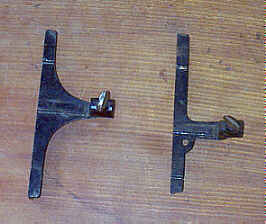
original #278 fence is to look at the
position of the hole for
the arm. If it's noticeably toward one side of the
casting, it's a #78 fence. In
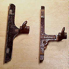
the image of the two fences, the #278's is the one to the left. An original #278 fence has its hole centered in
the casting. There
are no other holes in the fence.
The plane is almost entirely japanned. The thumb
screws and the lever cap
screw are nickel plated. The sides of the plane are milled
and have no
japanning. However, I have had an example of this tool that
has its milled
sides nickel plated. A tool pal of mine also reports a
similar nickeled
example. It's impossible to say whether the plane was plated
at a later date or
whether someone in New Britain was goofing around with some
leftover nickel at
the end of the day.
#282 Scraper, 13"L, 3"W, 1 5/8lbs, 1925-1958.
 An inexpensive floor
scraper, which I've included only as filler. Forget it -
it's ugly and
worthless, now that we have those 'lectrical floor sanders
at our renting call.
Still, the chef in you might find it very useful for
scraping your cast iron
griddle clean of pancake crusties.
An inexpensive floor
scraper, which I've included only as filler. Forget it -
it's ugly and
worthless, now that we have those 'lectrical floor sanders
at our renting call.
Still, the chef in you might find it very useful for
scraping your cast iron
griddle clean of pancake crusties.
The tool is a very simple construction - a wooden
handle (unfinished maple
until the mid-1930's, and from then on red painted hardwood
until it went belly
up) is attached to a japanned casting. On the backside of
the casting is a
maple block. Through both the maple block and the casting a
bolt passes with a
large washer and thumb screw to tighten the two pieces
together. Between the
casting and the wood block is a 1 3/4" by 3" scraper blade
that
projects to either side of the main casting by about 1/4".
The chunk of
wood helps to dampen the blade as you pull the tool toward
you. The wood often
becomes all beat to hell or split from years of hard floor
scraping.
The blade is normally fixed into the holder so that
the blade's cutting edge
is parallel with the casting's leading edge. However, the
blade can be pivoted
somewhat by turning the wood block toward one side and then
tightening it.
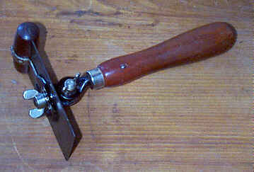
#283 Adjustable scraper, 9 1/2"L, 2 7/8"W, 2lbs, 1930-1941. *
 This is another
wierd invention of Stanley's, which really should have sold
more than it did.
It's a tough tool to find.
This is another
wierd invention of Stanley's, which really should have sold
more than it did.
It's a tough tool to find.
A turned tropical hardwood (the few I've owned are
either mahogany or cocobolo)
has a geared cast piece fitted into its business end. The
geared piece accepts
a similarly geared cast piece. Together, these two pieces
are screwed together
with a wing nut to allow the scraper blade to be adjusted
forward or backward.
The scraper blade is held in place by another wing nut, and
allows the blade to
be tilted from side-to-side. Because of the two degrees of
freedom, the scraper
can be configured for the hard to reach, awkward areas. It
was also advertised
as being useful for floor scraping, which I suppose is a
good thing for those
who are given to fits of living on their hands and knees.
The scraper blade is the typical blade used in the #12-type
scrapers, except it has a hole drilled through its center
so that it can be
attached indirectly to the handle. The Stanley logo is
stamped off-center,
toward one of the long edges of the blade. If you see one
that has the logo
situated elsewhere, be suspicious of it being a
replacement.
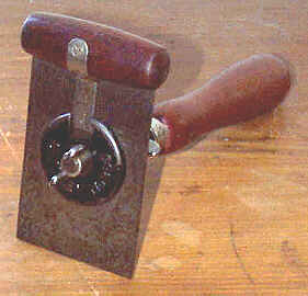 A wooden
grip,
as wide as the blade is wide, is kerfed to fit over the top
edge of the blade.
The grip has a metal strip screwed to it. The strip of metal
extends below the
grip and is curved so that it acts like a pressure spring to
keep the grip from
falling off. The grip can be pulled off so that the blade
can be sharpened. The
grip is often missing on the tool.
A wooden
grip,
as wide as the blade is wide, is kerfed to fit over the top
edge of the blade.
The grip has a metal strip screwed to it. The strip of metal
extends below the
grip and is curved so that it acts like a pressure spring to
keep the grip from
falling off. The grip can be pulled off so that the blade
can be sharpened. The
grip is often missing on the tool.
A washer-like cast iron piece is notched to fit
around the strip of metal.
This cast piece is what puts pressure on the blade when the
wing nut is screwed
tight. This cast iron piece has the number " No. 283" cast
into it.
Because of the length of the metal strip (attached to
the grip), and the
fact that it fits into the notch in the cast iron piece,
it's impossible to use
anymore than approximately 1.5" of the blade. The metal
strip could be
shortened by cutting it, but doing so decreases the amount
of tension it offers
to keep the grip in place. It's perhaps this design flaw,
along with the myriad
of other scrapers Stanley offered, that killed this tool
soon after it left the
drawing board.
The wing nuts have wings that are higher than normal
- sort of what you'd
expect if Mickey Mouse's ears paralleled Pinoccio's nose
whenever Mickey said
he likes the #55. The wing nuts are nickel plated, and the cast
iron parts are
japanned.
Several other manufacturers made a tool that looks
practically identical to
this one. Starrett, Miller Falls, and others were cranking
this thing out in
greater numbers than Stanley ever did, and examples by
manufacturers other than
Stanley are not valuable other than for use.
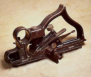
#289 Filletster and rabbet plane, 8 1/2"L, 1 3/4"W (1 7/8"W, 1936 on), 3 3/4lbs, 1911-1948. *
 This is one of Stanley's
nicest planes, in my not so humble opinion. It's sort of a
hybrid between the #78 and the #278. It looks more
like the common #78, except with the noticeable
difference in the
cutter's width and that the cutter is skewed. There are
also the two scoring
spurs, and a depth stop and fence that can be positioned
on either side of the
plane, like the #278's capability. The lever cap's screw, the depth
stop's thumb screw, and
the fence's thumb screw are the only parts that are nickel
plated on this tool.
The sides of the plane are machined flat so that it can be
used on its side.
This is one of Stanley's
nicest planes, in my not so humble opinion. It's sort of a
hybrid between the #78 and the #278. It looks more
like the common #78, except with the noticeable
difference in the
cutter's width and that the cutter is skewed. There are
also the two scoring
spurs, and a depth stop and fence that can be positioned
on either side of the
plane, like the #278's capability. The lever cap's screw, the depth
stop's thumb screw, and
the fence's thumb screw are the only parts that are nickel
plated on this tool.
The sides of the plane are machined flat so that it can be
used on its side.
This plane can also be found with an improper fence.
A proper fence has
web-like additions to the casting (for strength) where the
portion for the rod
meets the fence proper; the rod slips through the fence's
opening for it
roughly about mid-way along the fence's length. An
inordinate number of these
planes turn up fitted with fences from a #78. It seems odd that so many of
them would have lost
their fences over time. Perhaps Stanley ran out of #289 fences and sold #78 fences as
replacements for those guys who either lost or broke the
original fence. It's
hard to say for sure, but one thing is certain - the #78 fence is
not designed to work well on this tool when the plane is
configured for left-handed
planing. The fence has two holes, one front and one back,
so that an auxilary
wooden fence can be added to the plane.
 One thing to check on
this plane is that the arm unscrews easily and fits onto the
right side of the
plane. The arm has a hole drilled through its end so that a
nail can be
inserted through the hole to tighten the arm. The arm's
diameter of this plane
is larger than that of the #78's; the rod fills the hole in
its original fence, so
if you see a noticeable gap around the arm and the fence's
casting it's a good
bet that the rod isn't original. This isn't fatal to the
plane's function, but
if you're a collector you might experience a brain spasm
over it.
One thing to check on
this plane is that the arm unscrews easily and fits onto the
right side of the
plane. The arm has a hole drilled through its end so that a
nail can be
inserted through the hole to tighten the arm. The arm's
diameter of this plane
is larger than that of the #78's; the rod fills the hole in
its original fence, so
if you see a noticeable gap around the arm and the fence's
casting it's a good
bet that the rod isn't original. This isn't fatal to the
plane's function, but
if you're a collector you might experience a brain spasm
over it.
Also check that the spurs are ok, since the spurs
supplied with this plane
are unique to it (actually, the earlier models of the #10 1/4 use
the same spur, but these planes are far too expensive to
be used as a source
for replacement spurs). Each spur fits into a milled
recess, one on the left
and one on the right, and they are not interchangeable
with each other. Many of
the spurs are filed short so that they no longer can
protrude below the sole of
the plane. For a very brief time, Stanley made some of the
planes with the
three-lobed spurs that are identical to those used on the
#78 and
similar planes; this is the model to find, if you can.
 The lever cap, along
the
righthand edge can sometimes be found with a large chip out
of it. You should
also make sure that the lever cap is really a proper one for
the plane, and not
one that was lifted from a #78 (or similar plane) as a
replacement. A proper #289 lever cap has an S-shaped
reinforcement ridge along
its right edge (relative to its position in the plane).
The lever cap also has
the unusual feature in that it must be pulled upward so
that the lever cap
fulcrum screw can engage the cap. Nearly all the other
planes that use a
similar lever cap slip down over the lever cap fulcrum
screw, taking efficient
use of gravity. Perhaps the designer of the #289's lever cap was from the
southern hemisphere, the
moon, or some place like that.
The lever cap, along
the
righthand edge can sometimes be found with a large chip out
of it. You should
also make sure that the lever cap is really a proper one for
the plane, and not
one that was lifted from a #78 (or similar plane) as a
replacement. A proper #289 lever cap has an S-shaped
reinforcement ridge along
its right edge (relative to its position in the plane).
The lever cap also has
the unusual feature in that it must be pulled upward so
that the lever cap
fulcrum screw can engage the cap. Nearly all the other
planes that use a
similar lever cap slip down over the lever cap fulcrum
screw, taking efficient
use of gravity. Perhaps the designer of the #289's lever cap was from the
southern hemisphere, the
moon, or some place like that.
The earliest models of the plane have the patent date
embossed in the area
just behind the cutter's bed. While you're looking for that
date, to see if you
have an early one, be sure to check the area of the casting
that spans between
the handle and body proper as it can sometimes crack.
#292 Scraper, 12 1/2"L, 2 1/2"W, 1 1/2lbs, 1933-1964.
More filler for this rag. A cheap scraper used on floors, for removing paint, etc. It did come with a leather pad, under the blade, to eliminate chatter, if that's important to you.
#340 Furring plane, 10"L, 2"W, 2 1/2lbs, 1905-1917. *
 Yup, a plane designed to
remove fur, and a favorite among the PETA rank and file. Not
from animals, you
chucklehead, but from wood, as it came off the saw mill. How
would you like
that job, planing wood as it came off the saw? Too bad
What's My Line is off
the air. I woulda loved to hear Kitty Carlisle or Nipsey
Russell try to crack a
fur planer's rough exterior when giving him the third
degree.
Yup, a plane designed to
remove fur, and a favorite among the PETA rank and file. Not
from animals, you
chucklehead, but from wood, as it came off the saw mill. How
would you like
that job, planing wood as it came off the saw? Too bad
What's My Line is off
the air. I woulda loved to hear Kitty Carlisle or Nipsey
Russell try to crack a
fur planer's rough exterior when giving him the third
degree.
Judging by the length of time that this plane was
offered, you can tell that
fur planing was a popular pastime. Now, what is fur, in the
lumber sense? It's
the rough, fuzzy surface left from the sawing. Oftentimes,
the lumber was
chucked onto the ground before it was stickered. So, it was
like a dirt magnet.
Thus, some genius at Stanley, Rule and Level, Co. thought a
plane necessary to
tidy up the stock before a regular bench plane could be put
to the 'sullied' surface.
But that's the same function as the #40 and the #40
1/2. Or one
woulda thought so.
This plane is bizzare looking. When viewed from its
side, the plane's sole
makes contact only at its mouth and heel; between these two
points, the sole
arches upward. The toe is above the surface from just
forward of the cutter to
the toe's end. This wierd sole configuration, designed
purposely to minimize
the amount of contact with the wood, makes sworn members of
the Flat Plane
Society recoil in horror. If you ever stumble across one of
these planes, don't
bother trying to lap it, ok?
 Looking at the plane
from the top, the plane swells around the cutter's position,
and tapers both
toward the toe and heel so that the plane is lighter in
weight. It certainly is
a unique looking chunk of metal. The entire bottom casting
is japanned, save
for the flat sections of the sole below the tote and around
the mouth. The
plane's model number is embossed right behind the knob.
Looking at the plane
from the top, the plane swells around the cutter's position,
and tapers both
toward the toe and heel so that the plane is lighter in
weight. It certainly is
a unique looking chunk of metal. The entire bottom casting
is japanned, save
for the flat sections of the sole below the tote and around
the mouth. The
plane's model number is embossed right behind the knob.
The knob and tote are beech, and each is held to the
main casting with a
one-piece steel screw, and not the two-piece brass nut and
bolt that's used on
the common bench planes. The knob has a unique shape to it,
where it tapers in
diameter where it sits atop the casting. Stanley must have
thought that this
shape would lessen the knob's chances to split about the
base, but many of the
planes show splitting there. The same general shape to the
knob can be found on
the early #40 and #40
1/2 scrub
planes.
A single, thick cutter is used, and is held in place
by a simple cap and
screw. The cutter rests on a simple fin-like projection that
arises out of the
main casting. The first model of the plane has "PAT APLd
FOR" stamped
into the iron just below the Stanley logo. Since there is no
mechanical
adjustment means for the iron, the backside of the iron is
smooth. Any milling
in the backside of the iron means it's a replacement.
You only want to own one of these if you're a
collector. Many of them are
found in very tough shape since they did suffer hard work.
Finding the planes
in anywhere near new condition is very tough.
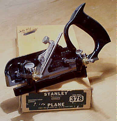
#378 Weatherstrip Rabbet plane, 8"L, 11/16"W (13/16"W, 1939 on), 2 5/8lbs, 1930-1958.
 One woulda thought that
Stanley had exhausted every possible design for a plane to
make the cuts for
weatherstrip installation. But no, the New Britain think
tank was in overdrive,
and nothing could stop it from polluting the hardware
shelves of America with
more offal. First the #78, then the #278, and now the #378, with this one is designed
specifically to cut the
rabbets for metal weatherstripping on meeting rails of
sash and for general
rabbetting within its capacity. Wonder why there was never
a #178 -
maybe they had one on the drawing board, but it
frightened its designers to death and thus never got into
production?
One woulda thought that
Stanley had exhausted every possible design for a plane to
make the cuts for
weatherstrip installation. But no, the New Britain think
tank was in overdrive,
and nothing could stop it from polluting the hardware
shelves of America with
more offal. First the #78, then the #278, and now the #378, with this one is designed
specifically to cut the
rabbets for metal weatherstripping on meeting rails of
sash and for general
rabbetting within its capacity. Wonder why there was never
a #178 -
maybe they had one on the drawing board, but it
frightened its designers to death and thus never got into
production?
This one looks like the common #190 rabbet plane, loaded with some
factory options -
there are three depth stops (one on each side that can be
set at different
depths) and a fence that is roughly one-third the length
of the plane. The
fence is carried by two arms each of which screws into the
main casting. Check
that the casting isn't damaged where the arms screw into
the plane.
An extra wide depth stop, positioned on either the
left or right side of the
plane, was provided for use on the wider cutters, which were
optional with the
tool. A thumb screw, just like the one used to secure the
slitting cutter on
the #45,
is used to secure the depth stop in place. The plane came
equipped with an
11/16" cutter, which was then upped to 13/16" from 1939
on. Optional
cutters could be purchased: 11/16", 3/4", 7/8", and 1".
 Two brass stop collars
are included so that pre-set positions of the rabbets can be
repeated from sash
to sash; the fence slams against these collars to maintain
the fence's
settings. These stop collars each have a small slotted screw
through them so
that the collars can be secured to the rear arm; the collars
are positioned so
that they 'sandwich' the fence. There is also a small cotter
pin that fits through
the rear arm. I have no idea what this pin does, other than
to make it
impossible for the fence to be removed from the arm - this
must be one of the
deep, dark secrets of weatherstripping that only a senior
member of WUA
(Weatherstripping Union of America) could answer. The astute
reader may quickly
realize that there are a lot of parts to this plane, and
they are usually MIA.
Two brass stop collars
are included so that pre-set positions of the rabbets can be
repeated from sash
to sash; the fence slams against these collars to maintain
the fence's
settings. These stop collars each have a small slotted screw
through them so
that the collars can be secured to the rear arm; the collars
are positioned so
that they 'sandwich' the fence. There is also a small cotter
pin that fits through
the rear arm. I have no idea what this pin does, other than
to make it
impossible for the fence to be removed from the arm - this
must be one of the
deep, dark secrets of weatherstripping that only a senior
member of WUA
(Weatherstripping Union of America) could answer. The astute
reader may quickly
realize that there are a lot of parts to this plane, and
they are usually MIA.
The plane is japanned with its sides machined flat.
The cutter is secured with
a nickel plated lever cap which is secured to the main
casting with a slotted
screw. The thumb screws to secure the fence and depth stops
are also nickel
plated. The fence has two holes drilled through it - one
near the front and the
other at the rear - so that a wooden face can be secured to
the fence. The
model number is embossed on the left side of the main
casting, just forward of
the handle.
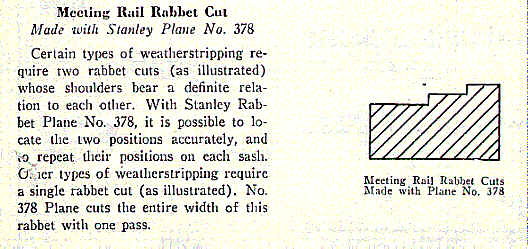
In one of Stanley's pieces of tool propagada - one
devoted to tools for
weatherstrip work - they indicate that this plane is "Used
to make the
rabbet cuts on the sash meeting rail and for all rabbet work
within its
capacity." If you don't know what the sash meeting rail is,
it's the two
rails that align with each other, on double-hung windows,
when the window is
closed.
You don't want this plane for working. Save it for
the collectors. Trust me
here.
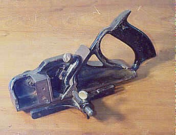
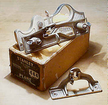
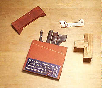
#444 Dovetail plane, 9"L, various widths, 6lbs, 1912-1938. *
 Runner-up to the Mr.
Stupid Plane Pageant (in the event that Mr. Stupid Plane can
no longer remain
in that role, the runner-up shall assume the position and do
guest appearances
either on a televised workshop program decorated in plaid or
Vegematic
infomercials). This is a plane that only a mother or Rube
Goldberg could love.
Runner-up to the Mr.
Stupid Plane Pageant (in the event that Mr. Stupid Plane can
no longer remain
in that role, the runner-up shall assume the position and do
guest appearances
either on a televised workshop program decorated in plaid or
Vegematic
infomercials). This is a plane that only a mother or Rube
Goldberg could love.
First, it's the most difficult plane to grip, if you
have large neanderthal
paws. A hollowed and looped opening in the casting is fit in
the palm, with
your fingers wrapping around it. The cutter sticks way up
into the opening
where it's perfectly positioned to rip apart the knuckles of
a careless
dovetailer. The toe, where you place your left hand, has a
little bump in the
casting, which is supposed to be sufficient for grasping.
Hah! I defy you to
use this plane without drawing puss or blood!
There are three main cast iron parts to the tool: 1)
the main casting, which
carries the cutter; 2) the fence, which makes the plane work
perpendicularly to
cut the dovetail in one position and also makes the plane
work at an angle to
cut the socket in another position; and 3) a depth stop,
which controls how
deep the shoulder of the dovetail is cut. The main casting
has two sets of
tapped holes in which the 2 1/2" arms are screwed. The main
casting also
has the patent information "PAT'S / 6-28 / 8-23 / 1910"
embossed on
the right side. Both the fence and the depth stop each have
two countersunk
holes drilled through them so that a wooden face may be
secured. The fence and
the depth stop each also carry two pressed steel stops that
are positioned to
one of the tick marks of the scales that are stamped into
each casting. These
scales help to set-up the plane correctly in order to get
the consistancy
needed to cut the corresponding dovetail and groove. The
steel stops butt up
against a blued 'bolt' that's positioned on the left side of
the main casting,
just above the cutter.
The plane cuts a flared (20 degrees) tongue and
groove, which most of us
recognize as a sliding dovetail. The plane's working range
is a groove no more
than 3/4" deep and dovetail necks no narrower than 1/4".
It's a very
difficult plane to describe how it's used in words, but I'll
take a stab at it.
The sole of the plane is beveled at 20 degrees. A fence is
provided that can be
attached to the plane on either side, to give different
results, depending upon
which side the fence is placed. In one case, the fence is
attached to the right
of the plane's main casting, making it work perpendicularly
to the edge (the
plane is cutting the tongue portion), and in the other, the
fence is attached
to the left of the plane's main casting to tilt it 20
degrees (the fence has
two faces, which oppose each other at 20 degrees) to cut the
groove. In the
latter case, the fence is used only to pitch the plane and a
batten must be
used, like a common dado plane, to guide it. When the plane
is used to cut the
tongue, a depth stop is fixed to the left side of the main
casting. When the
plane is used to cut the groove, the angled fence doubles as
a depth stop. The
grooves are the toughest to cut using this plane.
 The cutter is seated
at
a skew in the plane to facilitate cutting across the grain.
There are four
provided: 7/32", 3/8", 1/2", and 7/8". The cutter is
secured to the main casting via a plunger-like rod that's
activated by the
large thumb screw just forward of the grip. There are two
cast iron spur blocks
that are used to score the grain when working across the
grain; one spur block,
measuring 3/16" across the beveled face, is designed for the
narrow
cutters, and the other, measuring 5/16" across the beveled
face, for the
wider cutters. These spur blocks are secured to the right
side of the main
casting with two countersunk screws, just ahead of the
cutter. Another spur is
secured to the left side of the main casting. Since these
planes received very
little use, the spurs normally have plenty of length to
them, however, if you
find yourself in need of one, you can snarf them from the #289 or #10 1/4, both of which aren't low-cost
planes. Many of the
planes are missing cutters and one of the spur blocks.
The cutter is seated
at
a skew in the plane to facilitate cutting across the grain.
There are four
provided: 7/32", 3/8", 1/2", and 7/8". The cutter is
secured to the main casting via a plunger-like rod that's
activated by the
large thumb screw just forward of the grip. There are two
cast iron spur blocks
that are used to score the grain when working across the
grain; one spur block,
measuring 3/16" across the beveled face, is designed for the
narrow
cutters, and the other, measuring 5/16" across the beveled
face, for the
wider cutters. These spur blocks are secured to the right
side of the main
casting with two countersunk screws, just ahead of the
cutter. Another spur is
secured to the left side of the main casting. Since these
planes received very
little use, the spurs normally have plenty of length to
them, however, if you
find yourself in need of one, you can snarf them from the #289 or #10 1/4, both of which aren't low-cost
planes. Many of the
planes are missing cutters and one of the spur blocks.
The plane is entirely nickel plated, but even with
that, you'd still have to
be mighty desperate to own one of these (for use). Judging
by the number of
examples out there, most of which are in a remarkable state
of preservation,
with many in their original box, despair musta been oozing
from each and every
workshop that had this ghastly beast counted in its tool
arsenal.
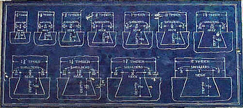
The earlier planes came in a finger-jointed wooden
box with a sliding top
while the later ones came in a cardboard box. Both boxes
have a bright blue
label, which shows the various dimensions of dovetails,
affixed to the
underside of the lid. A wooden box was provided to carry the
four cutters. The
box also has a diagonal line scribed across one face to
serve as a reference
for the proper grinding angle of the cutters. A sample
dovetail was also
commonly provided with the plane almost as if Stanley were
trying to prove to
the tool buying public that the plane actually works. We'll
never really know
for certain whether some unfortunate soul was chained to a
post in some New
Britain sweatshop, forced to use the plane all day long to
make the samples, or
whether a machine cut them and Stanley was pulling the wool
over Joe
Carpenter's eyes.
Stanley, in their catalogs, stated the plane could do
the following work
(tongue refers to the dovetail proper, while groove refers
to the socket):
- Dovetail tongue and groove joint with the groove cut in the regular manner, and the tongue cut on a bevel, used for supports.
- Dovetail tongue and groove joint with unequal shoulders, or a joint with a regular groove, but where the tongue is offset.
- Dovetail tongue and groove joint as can very often be conveniently used when one is forming and end to end timber match (like a scarf joint).
- Dovetail tongue and groove half joint, frequently used by carpenters to a very great advantage in concealed nail work.
- Dovetail tongue and groove joint where both the groove and tongue are cut on a beveled surface, making a strong corner.
- Dovetail tongue and groove joint for bracket support, where the bracket is dovetailed into the shelf.
- Dovetail tongue and groove joint as applied to the setting of gear teeth around the outer rim of any gear pattern.
[ START ] |
[ PREV ] | [ NEXT
] | [ END ]
[ HOME
]
Copyright
(c) 1998-2012 by Patrick A. Leach. All Rights Reserved.
No part may be
reproduced by any means without the express written
permission of the author.