The Superior Works: Patrick's Blood and Gore Planes #9 - #11 1/2
Quick Find:#9, #9 1/4, #9 1/2, #9 3/4, #10, #10C, #10 1/4, #10 1/4C, #10 1/2, #10 1/2C, #11 (belt), #11 (bull), #11 1/2
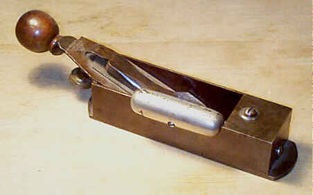
#9 Cabinetmaker's block plane, 10"L, (8 1/4" 1936 on), 2"W, 4 1/2lbs, 1870-1943. *
 This
plane has no number cast on
it. It is a rectangular, box-shaped plane sold as a high
quality tool designed
for the finer work of piano making and cabinet making. Its
sides are ground
flat and are square with the sole so that the plane can be
used on its side (to
function as a shooting plane and fine endgrain work) either
right or left
handed. The exterior of the tool is bare machined metal
while the inside of the
plane is japanned. The cutter is pitched at about 20 degrees
and is bedded in
the plane bevel side up.
This
plane has no number cast on
it. It is a rectangular, box-shaped plane sold as a high
quality tool designed
for the finer work of piano making and cabinet making. Its
sides are ground
flat and are square with the sole so that the plane can be
used on its side (to
function as a shooting plane and fine endgrain work) either
right or left
handed. The exterior of the tool is bare machined metal
while the inside of the
plane is japanned. The cutter is pitched at about 20 degrees
and is bedded in
the plane bevel side up.
It has a rear knob, made of rosewood, which is
secured onto a metal
extension that is itself screwed into the body of the plane.
Always check where
the body and the extension piece are screwed together for
stress cracks. The
force on the plane, as it's pushed, often breaks the casting
here.
The mouth is adjustable. There is a round-headed
screw on the top of the
tool, toward the throat, to set the mouth as fine as the
user wishes (within
its limits). If this screw is tightened too much, it can
crack the casting. A
washer was added to overcome this problem on later models.
There is a sausage-shaped and nickel plated side
handle, often called the
'hot dog', which attaches with a screw on either side of the
plane. This handle
is often missing, but the earliest model of the plane never
had it. There are
reproduction side handles available. The original handle is
easy to distinguish
from the reproduction - the original is cast and is hollow
inside whereas the
reproduction is milled from round stock and shows machining
marks inside it.
It's a good idea to remove the side handle before purchasing
the plane (unless
it's priced ridiculously low) to inspect the side rail for
any cracks or
missing chunks which the side handle can easily hide.
 The lever cap is
specially designed for this plane. It looks like a
conventional bench plane's
lever cap, but its neck (the narrowest part of the cap) is
longer than the
common lever caps used on the bench planes. Unscrupulous
dealers will use a #4 lever cap as a
replacement. Just make sure the pivot point of the lever
rests near the back
wall of the plane's body, where the handle extension
screws into the body. The
latest lever caps will have "STANLEY" cast into them.
The lever cap is
specially designed for this plane. It looks like a
conventional bench plane's
lever cap, but its neck (the narrowest part of the cap) is
longer than the
common lever caps used on the bench planes. Unscrupulous
dealers will use a #4 lever cap as a
replacement. Just make sure the pivot point of the lever
rests near the back
wall of the plane's body, where the handle extension
screws into the body. The
latest lever caps will have "STANLEY" cast into them.
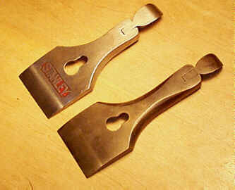
Like all the block planes made by Stanley, the cutter
for this model is
bedded with its bevel up. Since this plane used a
conventional bench plane
cutter, the company logo that's stamped at the heel (top) of
the iron isn't
visible when looking at the plane from above. Stanley would
stamp their logo on
some of the irons destined for this plane with the logo on
the bevel side as
well, making for irons that have the logo on both sides.
This same treatment
can also be found on the planes #11, #11
1/2, and #25.
The cutter has an adjustment mechanism based upon the
same style as that
used on the bench planes - a y-shaped fork engages a slot in
the 'cap iron' and
is adjusted by means of a brass nut. An early model of the
plane (up to the
late 1890's) has its brass nut travel in a direction
perpendicular to the heel
of the plane, whereas the later model has the brass nut
travel perpendicular to
the cutter. There was never a lateral adjustment mechanism
offered on the
plane.
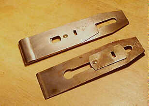 The 'cap iron' on this
tool is really not a cap iron, in the conventional sense,
like those used on
the bench planes. Instead, this 'cap iron' only serves to
engage the y-shaped
fork so that the cutter can take advantage of the patented
adjusting mechanism.
This 'cap iron' is a rectangular shaped piece of steel (the
short ends have a
small convex radius to them), about 1" x 2" in dimension.
The same
'cap iron' is also found on the #11, the #11 1/2, the #25, and the #164.
The 'cap iron' on this
tool is really not a cap iron, in the conventional sense,
like those used on
the bench planes. Instead, this 'cap iron' only serves to
engage the y-shaped
fork so that the cutter can take advantage of the patented
adjusting mechanism.
This 'cap iron' is a rectangular shaped piece of steel (the
short ends have a
small convex radius to them), about 1" x 2" in dimension.
The same
'cap iron' is also found on the #11, the #11 1/2, the #25, and the #164.
There are several very early examples of this tool,
when Leonard Bailey
himself was making them, which have markedly different
adjusting mechanisms
than the models that Stanley produced. The very first model
didn't come
equipped with any rear grip (no rosewood knob). The knob was
soon added,
probably soon after Bailey's complaint department was
flooded with death
threats from unhappy users of this plane - just looking at
it will make your
hands bleed.
This plane is modelled after similar English planes (Spiers-type)
and after the New York City area planemakers (Brandt, Erlandsen,
Popping, et al). While certainly a clever and nicely made
plane, it is a
distant runnerup when compared with those that inspired it.
It attempted to be
too much, when it didn't need to be. The other planes had no
contraptions for
adjusting their cutters - they excelled because they were
simple, well crafted,
and accurate.
#9 1/4 Block plane, 6"L, 1 5/8"W, 1 1/4lbs, 1947-1982.
 This is the first in a
series of block planes, which Stanley offered in practically
every shape and
color. Buying a block plane, as we are about to see, was
almost like buying an
automobile, where options galore were available to Mr.
Planebuyer of
yesteryear.
This is the first in a
series of block planes, which Stanley offered in practically
every shape and
color. Buying a block plane, as we are about to see, was
almost like buying an
automobile, where options galore were available to Mr.
Planebuyer of
yesteryear.
Stanley, in their marketing propaganda, claimed that
"A Block Plane
was first made to meet the demand for a Plane which could
be easily held in one
hand while planing across the grain, particularly the ends
of boards, etc. This
latter work many Carpenters call 'Blocking in', hence the
name 'Block' Plane."
This, if it is to be believed, dispells the
myth that block planes are so named because they were
first used on butcher's
blocks.
This is a general purpose block plane (one of many).
It has its iron bedded
at 20 degrees. The iron is adjustable both for depth and
lateral positions. The
mouth is non-adjustable, which is the distinguishing
'feature' that sets it
apart from the more useful #9 1/2. The fixed mouth of this plane
makes it rather
unpopular when pitted against Stanley's other block
planes, most of which have
adjustable mouths. The plane has a brass front knob that
screws into the main
casting - the knob is sometimes missing in action. The
area of the casting into
which the knob threads sometimes chips or cracks, and it
should be checked for
that damage, if you're collecting the thing, but if you're
using it, the damage
isn't severe enough to prevent the plane from working.
As is the case for most of the Stanley block planes,
the earliest models
were japanned (black). Later production planes were finished
with a very dark
blue paint starting in the early 1960's. The latest
production used a very deep
red as a finish. The same progression of paints can also be
found on the bench
planes.
Refer to the #9 1/2 for the details of construction, use, and
problem areas with this
plane, and most of the 20 degree pitch block planes that
Stanley cranked out in
all sorts of configurations.
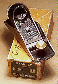
#9 1/2 Block plane, 6"L, 1 3/4"W (1 5/8"W 1909 on), 1 1/2lbs, 1873-1981.
 This
is a general purpose block
plane, and is probably Stanley's most popular one they
offered. Unless this
plane was your great grandpappy's, it's usually best to
ignore those examples
that are all rusted or are missing parts. It's such a common
plane (in its
post-1890's configuration) that you'll run across a better
example.
This
is a general purpose block
plane, and is probably Stanley's most popular one they
offered. Unless this
plane was your great grandpappy's, it's usually best to
ignore those examples
that are all rusted or are missing parts. It's such a common
plane (in its
post-1890's configuration) that you'll run across a better
example.
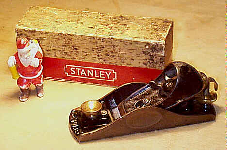
Pictured here, along with Santa Claus, is the typical
configuration of the
plane that you're likely to encounter (details below). The
box, with its faux
birch paper, is known as the Christmas box and was designed
to display the tool
in a hardware store setting during the Holiday Seasons of
the late 1940's and
early 1950's. Santa Claus was not shipped with the plane. An
unemployed
Salvation Army Santa - we found him roaming the streets
dejected - was offered
the opportunity to pose with the tool and graciously
accepted (note: Santa
isn't to scale, here).
The iron is placed into the plane bevel side up. An
iron that's oriented
bevel-up offers advantages when planing difficult woods or
endgrain; it's
possible to support a greater length of the iron, preventing
its flexing, on a
plane designed to carry its iron bevel-up than a plane
designed to carry its
iron bevel-down. The iron is pitched at 20 degrees. The
iron's pitch and
orientation make a cap iron unnecessary, and impractical for
that matter.
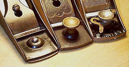
The plane underwent several modifications over its
long life. The first
model is a very primitive looking chunk of iron, with an
iron that extends up
and behind the tool making for a very uncomfortable grip.
This model has a flat
lever cap, with a cammed lever at its top, which resembles
the lever caps used
on the bench planes. The mouth piece is held in place with a
round-headed
screw. The arched sides of the plane's main casting are
curved irregularly and
are situated toward the back. This style of casting is often
referred to as the
'Excelsior' design.
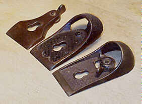 The discomfort of
using
the plane was soon addressed by the redesign of the lever
cap. The new lever
cap has a raised and curved portion cast at its back so that
it fits more
comfortably into the palm. It also has the characteristic
three arches cast
down near the leading edge of the cap along with a dimpled
exterior where the
palm rests. Even this new design was tough to grip since the
iron, with its
angular heel, was in the way. It wasn't until the
late-1800's when the heel of
the iron was replaced with a curved one.
The discomfort of
using
the plane was soon addressed by the redesign of the lever
cap. The new lever
cap has a raised and curved portion cast at its back so that
it fits more
comfortably into the palm. It also has the characteristic
three arches cast
down near the leading edge of the cap along with a dimpled
exterior where the
palm rests. Even this new design was tough to grip since the
iron, with its
angular heel, was in the way. It wasn't until the
late-1800's when the heel of
the iron was replaced with a curved one.
Various redesigns of the lever cap were made to
address its fragility and to
make it more comfortable. One such redesign placed the
cammed lever below the
lever cap so that it sits between the lever cap and iron.
This design suffers
breakage on the lever since it is relatively long in order
for it to be
accessible from below and behind the lever cap. During the
late-1890's, the
lever cap underwent its final modification, where the cammed
lever was made
accessible on top of the lever cap with the lever pointing
toward the toe (the
earliest examples can be found with "PAT'D 10-12-97" cast in
a circle
where the lever is pinned to the lever cap). This new design
allowed the length
of the lever to be reduced, thereby decreasing the
possibility of its breaking.
It also permitted the lever cap to be as long as the cutter,
eliminating its
arching upward, making for a more comfortable grip. It took
Stanley a while to
get to this point, but once they did, they stuck with it.
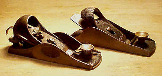 The model most often
encountered is the one offered from ca. 1895 onward. It is
distinguishable by
the oval depressions milled into the exterior of the arched
sides. These are
known as the "Hand-y" grip. The arched sides on most
examples are
symmetrical and are situated along the middle of the sides,
but there are some
examples of the Excelsior design that have the Hand-y grip.
The Hand-y grip feature
soon proved very popular, and was applied to practically
every block plane in
Stanley's arsenal. The feature was dropped for a short time
during WWII,
possibly because Stanley was using the machinery to mill the
same grip on
Howitzer shells so GI's wouldn't drop them on their feet.
The Hand-y grip was
also offered on a few of the shorter, handle-less
transitional (wood bottom)
planes, which are very rarely encountered.
The model most often
encountered is the one offered from ca. 1895 onward. It is
distinguishable by
the oval depressions milled into the exterior of the arched
sides. These are
known as the "Hand-y" grip. The arched sides on most
examples are
symmetrical and are situated along the middle of the sides,
but there are some
examples of the Excelsior design that have the Hand-y grip.
The Hand-y grip feature
soon proved very popular, and was applied to practically
every block plane in
Stanley's arsenal. The feature was dropped for a short time
during WWII,
possibly because Stanley was using the machinery to mill the
same grip on
Howitzer shells so GI's wouldn't drop them on their feet.
The Hand-y grip was
also offered on a few of the shorter, handle-less
transitional (wood bottom)
planes, which are very rarely encountered.
Prior to the patent for the lateral adjustment
mechanism, as specified for
the common bench planes, these block planes only permitted
the iron to be
adjusted endwise to regulate the depth of cut. The earliest
mechanism is a
lever, located beneath the iron, which engages stopped
parallel grooves milled
into the back of the iron via a vertical pin. Moving the
lever laterally
side-to-side, raises or lowers the iron. It also puts a lot
of stress on the
pin, which can snap it off or wear it away. Plus, the lever
also has a pin on
its bottom to slip into a hole in the boss that carries it.
Because it's not
permanently attached to the plane, it's possible to find
planes with this lever
missing in action.
 This mechanism proved
to
be rather fragile and was difficult to access so Stanley
redesigned it. The
solution that they came upon is a threaded post adjustment
mechanism and
started offering it during the early 1880's. This post is
screwed into a raised
boss in the main casting. On the post a brass nut traverses
up and down, parallel
to the sole, as the nut is turned. The nut engages a forked
lever, which in
turn engages the grooves in the back of the cutter. As the
nut is turned to
move it upward, the lever lowers the cutter to increase its
set. Moving the nut
downward, naturally, decreases the set. Make sure that this
nut moves freely
over the entire length of the threaded post.
This mechanism proved
to
be rather fragile and was difficult to access so Stanley
redesigned it. The
solution that they came upon is a threaded post adjustment
mechanism and
started offering it during the early 1880's. This post is
screwed into a raised
boss in the main casting. On the post a brass nut traverses
up and down, parallel
to the sole, as the nut is turned. The nut engages a forked
lever, which in
turn engages the grooves in the back of the cutter. As the
nut is turned to
move it upward, the lever lowers the cutter to increase its
set. Moving the nut
downward, naturally, decreases the set. Make sure that this
nut moves freely
over the entire length of the threaded post.
Stanley decided to have some fun with these adjusting
nuts, as some are a
right hand thread while others are a left hand thread.
Almost all of the planes
with the Hand-y grip have the left hand thread. All the
Excelsior style planes
have a right hand thread. This tidbit of information is only
important if
you're looking for replacement parts for the adjusting
mechanism, or if you're
looking for the locking nut used on the #9 3/4 and #15
1/2.
You want to be sure that the two nibs on the fork,
where they engage the
parallel machined grooves cut into the backside of the
cutter, are not broken
or worn away. Otherwise, the adjustment mechanism is
useless. Also, check about
the boss that receives the threaded post for any breakage.
Sometimes, the post
loosens over time; usually, just by wiggling the post you
can tell whether it
is seated into the boss well. It can be tightened by
screwing it back into the
boss, but take care not to damage its threads.
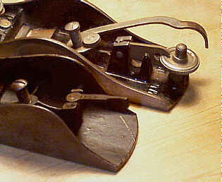
The lateral adjustment lever that was a raging
success on the bench planes
was a feature that the block planes could also use. It took
Stanley a bit of time
to add the lever, but they eventually did during the early
1890's.
The lateral adjustment lever pivots on the lever cap
screw, onto which the
lever cap engages. In fact, the lever screws onto the lever
cap screw, which is
itself screwed into a boss in the main casting. The lateral
adjustment lever
has a disk at its end nearest the mouth, and it fits into a
slot cut into the
iron. It very much resembles the business end of the lateral
adjustment lever
found on the common bench planes. The back of the lever is
bent downward, in a
gradual curvature toward the sole so that it doesn't dig
into your hand during
use. Sometimes, the lateral adjustment lever has been bent
so that it can't
clear the threaded post. If this is the case, you can simply
bend the lateral
lever about its downward curve up a bit so that sufficient
clearance results.
The lateral adjustment lever often has its patent date
and/or
"STANLEY" stamped into it.
 The earliest planes
have
an adjustable mouth that uses a slotted screw - you'll need
a screwdriver to
adjust it, if you dare to use this most valuable model of
the tool. This clumsy
adjustment method certainly must have flooded the complaint
department at
Stanley, so the mouth was made adjustable by means of a
brass knob (the
presence of nickel plating signifies that it's a different
model). The knob is
threaded to the sliding section, and by unscrewing the knob
the sliding section
can be moved forward or backward. The knob is then tightened
to lock the
sliding section in place. You should check the threads of
the knob to make sure
they aren't stripped for if they are, your sliding section
will slip out of
your sole and possibly into oblivion.
The earliest planes
have
an adjustable mouth that uses a slotted screw - you'll need
a screwdriver to
adjust it, if you dare to use this most valuable model of
the tool. This clumsy
adjustment method certainly must have flooded the complaint
department at
Stanley, so the mouth was made adjustable by means of a
brass knob (the
presence of nickel plating signifies that it's a different
model). The knob is
threaded to the sliding section, and by unscrewing the knob
the sliding section
can be moved forward or backward. The knob is then tightened
to lock the
sliding section in place. You should check the threads of
the knob to make sure
they aren't stripped for if they are, your sliding section
will slip out of
your sole and possibly into oblivion.
During the late-1890's, an eccentric lever was
provided to adjust the mouth
(the earliest examples will have the patent date, "PAT FEB
20 94",
stamped in them). This little device soon was applied to
every block plane that
was equipped with an adjustable mouth. It's really a simple
little device - a
flat piece of steel, with an extension for your finger,
pivots on a pin which
fits into a hole behind the knob. This piece is not held
captive to the plane,
and it's very easy to lose. If you see a small hole
immediately behind the
knob, your plane is missing its eccentric lever. Also be
sure to check the eccentric
lever to see if it has its post that fits into the casting.
Strangely, many of
the levers are still on the planes but don't have the post.
You should check that the eccentric lever is proper
for the plane by sliding
it to the left and right, making sure that the sliding
section of the sole
moves within the acceptable range. Because this lever was
often removed from
the plane (the owner simply found it easier to adjust the
sole without it), and
because the same lever was offered on the smaller block
planes, it's sometimes
possible to find planes with an improper lever - a lever
from the smaller #60 1/2 will not
permit the sole to be adjusted over as wide a range as a
proper one will.
 The sliding section of
the sole is oftentimes jammed into the plane so that it no
longer moves freely.
The usual cause of this is that either oxidation has frozen
it in place or that
crud has become lodged between it and the main casting. To
overcome this common
problem you first need to free the sliding section from the
main casting. This
is easily done by first backing off the knob that holds it
in place with a few
turns, then pushing the knob downward with your thumb. The
piece should pop
free, but if it doesn't, take more drastic measures like
penetrating oil or
light taps from a hammer. Save the dynamite as last resort.
I've never found
one that ultimately didn't come free with a piece of wood
(stood on its
endgrain) positioned in the mouth (from the top of the
plane) and then tapped
with a hammer.
The sliding section of
the sole is oftentimes jammed into the plane so that it no
longer moves freely.
The usual cause of this is that either oxidation has frozen
it in place or that
crud has become lodged between it and the main casting. To
overcome this common
problem you first need to free the sliding section from the
main casting. This
is easily done by first backing off the knob that holds it
in place with a few
turns, then pushing the knob downward with your thumb. The
piece should pop
free, but if it doesn't, take more drastic measures like
penetrating oil or
light taps from a hammer. Save the dynamite as last resort.
I've never found
one that ultimately didn't come free with a piece of wood
(stood on its
endgrain) positioned in the mouth (from the top of the
plane) and then tapped
with a hammer.
Once free, clean out any of the crud that's
accumulated over the years.
Check that the boss cast into the sliding section, which
receives the knob,
isn't broken. Curiously, many of them are.
If the sliding section doesn't move freely, you can
do a bit of plane
surgery to remedy the ailment. With some fine abrasive paper
on a flat surface,
rub the edges of the sliding section back and forth a few
times to remove any
oxidation or burrs. Take the same paper and rub the milled
tracks of the main
casting. Don't overdo it since you will introduce some slop
in what's usually a
fine fit. Reattach the part to the main casting and it will
slide freely.
 Make sure that the
sliding section hasn't been modified, where the portion
that's closest to the
iron isn't ground. For some strange reason, some of these
block planes can be
found with their sliding sections ground shorter than when
they left the
factory. Planes with modified sliding sections will not be
capable of having
their mouths set finely. The sliding section should nearly
touch the iron when
the section is moved backward to close the mouth. If it
doesn't, the piece has
been ground. If you do have an example with a ground sliding
section, and are
planning to locate a replacement part, take care when doing
so; the replacement
section my be too thick or thin, and not lie in the same
plane as the rest of
the sole. I've yet to find a block plane that can accept a
sliding section
taken from another block plane without some modification.
Make sure that the
sliding section hasn't been modified, where the portion
that's closest to the
iron isn't ground. For some strange reason, some of these
block planes can be
found with their sliding sections ground shorter than when
they left the
factory. Planes with modified sliding sections will not be
capable of having
their mouths set finely. The sliding section should nearly
touch the iron when
the section is moved backward to close the mouth. If it
doesn't, the piece has
been ground. If you do have an example with a ground sliding
section, and are
planning to locate a replacement part, take care when doing
so; the replacement
section my be too thick or thin, and not lie in the same
plane as the rest of
the sole. I've yet to find a block plane that can accept a
sliding section
taken from another block plane without some modification.
By far the most common damage found on the plane, as
well as on all models
of block planes, is stress cracks that run from the mouth
and up the side(s) of
the tool. These cracks are most often found on the earlier,
pre-1890's, models
since their sides are not cast to a uniform thickness; they
taper along their
edge just like the earlier bench planes do. This was a very
common area for the
plane to break so Stanley made the later models with their
sides cast to a
uniform thickness. Often, these stress cracks are invisible
under the
oxidation. It's only when you give them a cleaning that you
notice the damage.
Don't sweat it if yours is broken here - you're not the
first, nor will you be
the last, to buy such damaged goods.
Another common form of damage is cracks or breaks to
the lever cap, in the
area where it arches to fit into your palm. Cracks here are
really no big deal,
but missing chunks might yield bloody palms. Fortunately,
there are plenty of
lever caps that can be salvaged from the googleplex of block
planes out there.
The planes have a japanned finish, with the brass
knob and depth adjusting
nut all buffed to shine. The lateral adjustment lever and
eccentric lever are
often nickeled, but later ones are just stamped from steel
and buffed. The
plane commonly has its model number stamped into the left
side of the main
casting, down toward the sole. None of the Stanley block
planes came with
corrugations milled into the sole. A few of the mid-1920's
planes can be found
with the day-glo orange paint on the eccentric adjuster and
inside the front
knob. This had to be a phase that Stanley was going through
as some of the
contemporary bench planes have the sides of their frogs
finished with the same
color paint.
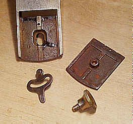
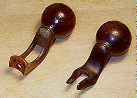
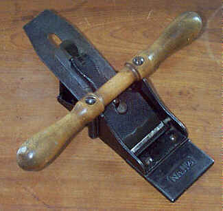
#9 3/4 Block plane, 6"L, 1 3/4"W (1 5/8"W 1909 on), 1 5/8lbs, 1873-1934. *
 This
plane is identical to the #9 1/2, except that it
has a detachable rear handle. The handle is a metal
extension that fits around
and is fixed to the same threaded vertical post that the
depth adjustment nut
is. A locking nut is screwed onto the post and then is
tightend over two metal
prongs on the handle. The handle can be removed to suit
the workman's use
simply by backing off the locking nut with the end of a
screwdriver. The
locking nut has four "lobes" on it making it resemble an
"x".
This
plane is identical to the #9 1/2, except that it
has a detachable rear handle. The handle is a metal
extension that fits around
and is fixed to the same threaded vertical post that the
depth adjustment nut
is. A locking nut is screwed onto the post and then is
tightend over two metal
prongs on the handle. The handle can be removed to suit
the workman's use
simply by backing off the locking nut with the end of a
screwdriver. The
locking nut has four "lobes" on it making it resemble an
"x".
Because Stanley was never satisfied to leave well
enough alone, they changed
the width of the boss onto which the pivotting lever (the
one that engages the
underside of the cutter) fastens. This subtle design change
meant a similar
change in the detachable handle; the distance between the
two prongs had to be
increased just a hair so that the prongs can slip around the
boss. This minor
point is only mentioned in the event that you have a handle
and you're trying
to fit it to a plane. Do not ever force the handle or file
it if it doesn't fit
- you have an earlier two prong handle that needs to go on
an earlier version
of the plane.
 The metal extension
has
a turned rosewood knob that fits into the palm of the hand,
allowing the plane
to be worked more comfortably with both hands. The earliest
versions of the
plane use the common threaded rod and brass nut to secure
the rosewood knob to
the the extension piece. On later models, the rosewood knob
is tapped and
screws directly onto the threads cast into the metal
extension. On these later
models, the knob can strip and become loose over time. The
usual quick fix was
to jam a shaving or a piece of cloth into the knob and then
allow friction to
work its magic.
The metal extension
has
a turned rosewood knob that fits into the palm of the hand,
allowing the plane
to be worked more comfortably with both hands. The earliest
versions of the
plane use the common threaded rod and brass nut to secure
the rosewood knob to
the the extension piece. On later models, the rosewood knob
is tapped and
screws directly onto the threads cast into the metal
extension. On these later
models, the knob can strip and become loose over time. The
usual quick fix was
to jam a shaving or a piece of cloth into the knob and then
allow friction to
work its magic.
Prior to the introduction of the threaded vertical
post, the metal extension
piece was screwed right to the main casting, beneath the
iron. This model is
comparatively scarce, and was only made for a few short
years. It can be
identified easily by a screw hole at its end and an open
casting that gives the
appearance of two ribs projecting from the knob. This style
of handle was used
only on the two earliest models of the plane, from 1872 to
about 1875. Check
these handles carefully for cracks over their length.
Most of the metal extensions are japanned, but the
very earliest ones have a
copper flashing to them, which is usually long gone and hard
to find today. Be
careful that the knob is proper, and not one lifted from a
#45. The #45's knob
(referring to the model that threads the knob onto the
fence's casting in the
same manner as it is on the block plane's extension handle)
is a hair small in
its diameter and doesn't have the ring turned at its base.
#10 Carriage maker's rabbet plane, 14"L (13"L 1887 on), 2 1/8"W, 4 1/4lbs, 1870-1957.
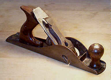 This plane is sometimes
called the 'jack rabbet' due to its similarity to the common
jack plane. It
looks identical to a conventional #5, except that it has a rabbet
mouth. The rabbet
mouth is two cutouts in the plane's sides, just to the
left and right of the
iron. The iron extends through these cutouts and across
the entire width of the
sole. These planes have always been popular, with their
full adjustment
features identical to those found on the bench planes.
This plane is sometimes
called the 'jack rabbet' due to its similarity to the common
jack plane. It
looks identical to a conventional #5, except that it has a rabbet
mouth. The rabbet
mouth is two cutouts in the plane's sides, just to the
left and right of the
iron. The iron extends through these cutouts and across
the entire width of the
sole. These planes have always been popular, with their
full adjustment
features identical to those found on the bench planes.
They were used for cutting large rabbets in heavy
timbers for framing in the
mining, carriagemaking, etc., professions. Since the plane
has a rabbet mouth,
and because it was designed for heavy use, many of them have
stress fractures
in the casting right above the rabbet mouth, where the sides
arch upward. Many
of them have been repaired with a welding, which sticks out
like a sore thumb,
usually, but some repairs are very good and can go
undetected. The planes also
seem to suffer chipping/cracking along their side walls,
especially about the
toe and heel. The earlier models, with their tapered side
walls, are more prone
to this chipping/cracking than the later ones are.
Another thing to check on these planes is their
irons. Because of the rabbet
mouth, there isn't nearly enough space to make an iron that
is as long as those
found on the conventional bench planes - the sides of the
plane prevent it from
being as long as the others. Be sure to check that there is
enough 'meat' or
life left to the iron. Finding replacements that are proper
to the vintage of
your plane can be tough. Also, the cap iron should cover the
full width of the
iron along the cutting edge. If it doesn't, it's a
replacement from a normal
bench planes.
Removing the irons from this plane, and the #10 1/2, is a bit of a trick. They
cannot be removed
through the mouth, and they are prevented from being
removed as you normally
would an iron by the sides of the plane. To remove the
iron, then, you must
first tip it up so that it clears the lever cap screw,
then slide it to either
side of the plane, and then lift the opposite side up,
sort of in a twisting
fashion, until one side of the iron clears the cutout in
the side of the plane.
Stanley recognized the problem with removing or
returning the iron from or to
the plane. Returning the iron to the plane needs a bit of
attention so that you
don't nick the edge, ruining the honing effort that took you
hours to get. To
overcome this problem, Stanley redesigned the cap iron and
the way it was
attached to the iron. A small screw was positioned on top of
the cap iron so
that once removed, the iron would slip through the mouth
easily. Problem
solved, or so Stanley thought. This short-lived (ca. late
1880's) feature
proved to be a problem when reassembling the iron - trying
to position the cap
iron properly on the iron, while both are in the plane
proved to be awkward and
difficult. They soon dropped the design for the normal
method of attaching the
cap iron (the screw is behind the iron and is only
accessible with the iron
removed from the plane).
These planes, along with the fractional versions of
it, never came equipped
with the frog adjusting screw that's found on the bench
planes. In fact, all
the frog redesigns made to the bench planes never made it to
this line; the
bench rabbets retain their flat mating surfaces between the
frog and the main
casting. However, the planes did follow the changes made to
the lever cap, the
adjusting screw, the knob, and the tote that were done to
the bench planes (see
their type study for more features).
As is the case with all rabbet planes, a batten is
normally fastened to the
work at the desired with of the rabbet. The batten then
guides the plane along
its path to yield a straight cut. The depth of the rabbet is
normally marked with
a common marking gauge. For cross grain work, the rabbet's
shoulder is usually
cut with a saw prior to using the plane since this plane
doesn't come equipped
with a spur to score the grain.
If you ever need a lever cap for this plane, or the
other bench rabbets that
follow, the #3's will work. The old style #3 frog also fits the
plane; i.e., the frog that
doesn't have a notch (to fit over the alignment rib in the
main casting) milled
at its lower edge.
#10C Carriage maker's rabbet plane, 14"L, 2 1/8"W, 4 1/4lbs, 1902-1918. *
The corrugated version of the #10. A brute of a dude, who had taken to planing rabbets in heavy timbers as a career, certainly didn't need any 'girlie-man' corrugations in the sole to make his job any easier. This may be one of the reasons for the scarcity of the corrugated model of this plane.
#10 1/4 Carriage maker's rabbet plane, 13"L, 2 1/8"W, 4 1/4lbs, 1911-1942. *
This plane is identical to the #10, except that it has a tilting tote and knob. This idea was first patented by a guy who added tilting wood to regular #10's because he found that your knuckles got all smashed when planing large rabbets. Stanley, being the nice guys they were to their competition, decided they could do it themselves, and made their own version of it thereby making the originator of the idea a footnote in the history of planes.
The tote and knob each sit atop a rounded casting
that holds a coarsely
knurled metallic cylinder. The usual securing rods for the
tote and knob are
screwed into these knurled cylinders. At the top of each
securing rod is a
slotted nut, which is tightened to secure the tote and knob
in a slanted
position, tilted from the vertical, that the user finds
comfortable. The
slotted nuts are often mangled from repeated use.
Often the wooden parts, especially the lower portion
of the tote, are found
cracked or broken off around their bases from years of use.
The wooden parts
are custom made for this plane, so trying to salvage a tote
or a knob from a
standard jack plane is pointless; original totes and knobs
have a concave bottom
so that they can fit over their respective convex portions
of the main casting.
The same problem of stress fractures about the sides
of the bottom casting,
as found on the #10,
also happens with these planes.
Two retractable spurs, one on each side of the plane,
are used to score the
wood before the iron cuts it. These spurs help to eliminate
ratty edges on the
rabbet, especially when working across the grain. The spurs
are attached to the
plane with small countersunk screws. The screws often show
signs of mangling
from repeated use. The earliest models of this plane do not
have these spurs.
It's interesting that Stanley only offered these spurs on
this plane, and not
the other bench rabbet planes. Perhaps they realized that
they made a mistake
by offering this tool and to save face they added the spur
feature to boost
sales by making them really different from the #10 and #10 1/2. Sounds good to me, at least.
In any event, the
spurs certainly assist the plane when cutting across the
grain, making for a
clean shoulder.
I've seen a WWII model of this plane, where hard
rubber, instead of brass,
was used for the cutter's depth adjustment knob and the tote
and knob are hardwood
instead of rosewood. There is no nickel plating on the lever
cap. With this
plane's sales being rather anemic from its introduction, it
seems strange that
Stanley would even make a Warlwartwotype (pronounced
properly as a single
syllable). Planing large timbers during WWII certainly had
to be a lost 'art'
in the States, but maybe not so in the Orient. Perhaps
Stanley kept up the
production of the plane in anticipation of the building of a
bridge over the
river Kwai, or something?
#10 1/4C Carriage maker's rabbet plane, 13"L, 2 1/8"W, 4 1/4lbs, 1912-1917. *
Corrugated version of the #10 1/4. Putting corrugations on a plane, which probably was better left on the drawing board in the first place, makes for a very rare plane. This is a tough one to find, one of the toughest of all Stanley planes, so be careful of the modern artisan's craftiness.
#10 1/2 Carriage maker's rabbet plane, 9"L, 2 1/8"W, 3lbs, 1885-1964.
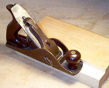 This
is sometimes called the
'smooth rabbet' since it is the same size as a #4, however in some of Stanley's
earlier propaganda
this plane and the #10 are both simply called a
"Carriage Maker's
Rabbet". The usual problems with the #10, and the other bench planes,
are also found on this
guy. The most common form of damage are cracks and/or
repairs to the cheeks of
the tool, located just above the cutouts for the cutter.
This
is sometimes called the
'smooth rabbet' since it is the same size as a #4, however in some of Stanley's
earlier propaganda
this plane and the #10 are both simply called a
"Carriage Maker's
Rabbet". The usual problems with the #10, and the other bench planes,
are also found on this
guy. The most common form of damage are cracks and/or
repairs to the cheeks of
the tool, located just above the cutouts for the cutter.
The earliest models have an adjustable mouth, very
much like those found on
the common block planes, but the entire section of the sole
ahead of the iron
moves. Adjustable mouth versions are much scarcer than the
non-adjustable mouth
versions, and were only offered for about the first ten
years of the plane's
production.
The mouth is adjusted by turning the front knob,
sliding the knob forward or
backward, and then tightening the knob; this action moves
the entire sole ahead
of the iron. The casting that receives the front knob's
screw is sometimes
broken so take the plane apart to inspect this. The
repetitive adjustment to
the mouth also puts wear and tear on the rosewood knob; many
of them are split
or are chipped at their bases. I've seen some of these early
models with a
metallic disk under the knob in an attempt to overcome the
chipping that the
knobs suffer; this disk appears original and is similar to
the one used on the #62.
This plane always came with the lateral adjustment
lever - if you see one
that doesn't have one, it's likely from an earlier #3 or #10.
#10 1/2C Carriage maker's rabbet plane, 9"L, 2 1/8"W, 3lbs, 1902-1917. *
Corrugated version of the #10 1/2. It never came with an adjustable mouth, to the best of my knowledge. Because this plane is much more valuable than its non-corrugated brother, be careful of counterfeit corrugations.
#11 Beltmaker's plane, 5 3/4"L, 2 3/8"W, 3 1/2lbs, 1867-1943.
 Hey,
if you're into making, or
repairing, the belting used for driving machinery, get with
it, will ya? We're
about to enter a new century never mind a millenium, too!
But for those of you who
want the frightening details, read on....
Hey,
if you're into making, or
repairing, the belting used for driving machinery, get with
it, will ya? We're
about to enter a new century never mind a millenium, too!
But for those of you who
want the frightening details, read on....
The cutter is positioned bevel side up, and is bedded
~25 degrees. There is
no cap iron proper on the plane, but it does have a small
cap screwed to the
top of the cutter, like the #9, #25, and #164 do, so that the tool can take
advantage of the
Bailey adjustment features like those found on the common
bench planes. The
y-shaped adjusting fork engages a slot in the small cap.
This slot is oriented
toward the heel, not the cutting edge, of the iron.
It seems that those who practiced the beltmaking
trade were a trifle bit
spastic - many of these planes have broken adjusting forks.
This problem
resulted from insufficient pressure, via the lever cap,
being placed on the
iron, when it had a rank set. When the iron started its cut,
it immediately
jumped backward which then strained the adjusting fork where
it makes contact
with the brass depth adjustment knob, causing it to snap. If
you plan to
resurrect the beltmaking trade, and your plane has a broken
adjusting fork, you
will have to replace it with a fork from another #11 (or #11 1/2) - the adjusting forks from
the bench planes are
not interchangeable with this model.
Sometimes, insufficient pressure on the iron will
cause the back part of the
casting to snap off or crack, where the threaded rod fits
into the casting.
Broken chunks off the casting are easy to spot, but to see
the stress cracks
takes a keener eye. Look closely about the rear of the
plane. Take the iron out
of the plane and look (from the inside of the casting) where
the rod meets the
casting to see if any stress cracks have developed.
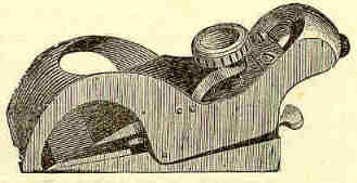
The plane looks very similar to the #12, and has a turned hardwood
(most often maple)
handle that is perpendicular and parallel to the plane's
sole. The handle is
screwed to the plane's main casting with two round-headed
srews, each of which
screws into a cast boss. Check that these bosses are not
chipped or cracked.
The cutter is secured in place by a lever cap that is
identical to those
used on the transitional wooden bench planes (see their
listing for a
description). The entire main casting, except its sole and
the machined bed,
are japanned.
 The mouth is
adjustable
to satisfy the beltmaker's craving for tearout free planing,
something that's
mandatory when planing leather or fabric belting. NOT! A
small casting
functions as the sliding section found on the common block
planes. It's secured
to the main casting with two round-headed screws, which when
loosened, allow
the sliding section to be moved forward or backward manually
as the village
beltsmithy so desires.
The mouth is
adjustable
to satisfy the beltmaker's craving for tearout free planing,
something that's
mandatory when planing leather or fabric belting. NOT! A
small casting
functions as the sliding section found on the common block
planes. It's secured
to the main casting with two round-headed screws, which when
loosened, allow
the sliding section to be moved forward or backward manually
as the village
beltsmithy so desires.
Oh yeah, why a belt plane? Simple, back before
'lectricity and infernal
combustible engines, water wheels and steam engines supplied
the power to drive
Industrial America (and other joints). Leather and/or fabric
belts were used to
drive the smaller machines off the power source. These belts
have their ends
fastened to each other to form a loop, and it's at the
juncture of the two ends
that a chamfer is cut so that when the ends are fastened
they maintain the same
thickness as the rest of the belt. You had to ask.
This plane was originally offered by Leonard Bailey
prior to his selling out
to The Man, Stanley. His first design is extremely rare. He
eventually made the
plane with a separate frog that is secured onto the main
casting with two
round-headed screws. The threaded rod, on which the brass
depth adjusting screw
rides, is oriented nearly vertically. This construction
proved costly to
manufacture, and the planes were prone to damage, especially
cracks or breaks
where the screws are, so the separate frog idea was dropped
around 1905. The
tool was redesigned with the threaded rod fastened directly
to the main casting
so that it's oriented horizontally. The earliest models of
this tool have a
fair concave curvature to their side walls from the toe of
the plane to the
handle. The later models have a sort of contorted S-shaped
curvature to the
side walls.
#11 Bull Nose Rabbet Plane, 4"L, 1 1/4"W, ca 1880. *
 This
is really a strange little plane, in several ways. First, it
wasn't offered in
any Stanley catalog, and judging by where the very few
specimens have turned
up, in England, the plane wasn't sold here in USofA. Second,
this plane's
number designation is identical to the beltmaker's plane,
making these two the
only planes offered concurrently with the same model number.
Why Stanley chose
to designate them the same is anyone's guess, and it's
certainly odd given
Stanley's passion for freely assigning numbers, which the
last time I checked
are infinite, to their manufactured wares. The plane is one
of the very rarest
of Stanley's planes, with only a handful of extant examples.
When other folks
are classifying #340's,
#64's as very rare,
and #3C's
as very scarce, you can ask them how they'd classify this
little bugger then.
This
is really a strange little plane, in several ways. First, it
wasn't offered in
any Stanley catalog, and judging by where the very few
specimens have turned
up, in England, the plane wasn't sold here in USofA. Second,
this plane's
number designation is identical to the beltmaker's plane,
making these two the
only planes offered concurrently with the same model number.
Why Stanley chose
to designate them the same is anyone's guess, and it's
certainly odd given
Stanley's passion for freely assigning numbers, which the
last time I checked
are infinite, to their manufactured wares. The plane is one
of the very rarest
of Stanley's planes, with only a handful of extant examples.
When other folks
are classifying #340's,
#64's as very rare,
and #3C's
as very scarce, you can ask them how they'd classify this
little bugger then.
The plane has a lever adjustment mechanism, identical
to that used on the
common #103 block
plane; a series of
parallel grooves is milled into an adjusting plate, which,
in turn, engage
milled slots cut in the backside of the blade. A thumb
screw pivots the lever
cap to hold the blade in position.
The final strange thing about this plane is that the
small portion of sole,
directly ahead of the blade, can be raised or lowered via
two small set screws
which sit behind the lever cap's thumb screw. This portion
of the sole is
adjusted to work harmoniously with the set of the blade;
i.e., if the blade is
set rank (deeply), the sole is raised, and if the blade is
set fine, the sole
is lowered. This function lends assistance to the plane's
cutting action, for
if the sole were at a constant position, only a minute
portion of it would bear
upon the wood during the planing; the deeper the blade's
set, the less amount
of sole will make contact with the wood. Because the sole
ahead of the iron can
be adjusted, it's practical to make the entire length of
that sole make contact
with the wood prior to the blade's cutting, reducing tearout
and splintering.
It's a geometry thing, here.
The plane was eventually dropped when the #90 cabinetmaker's bull nose rabbet plane
appeared. No sense having two
planes serve the same function, or so one would think.
But, Stanley didn't
adopt this "modus operandi" for too long as they
ultimately produced
concurrently several planes which served the same
function.
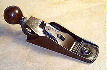
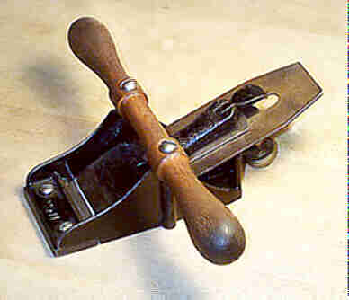
#11 1/2 Floor plane, 7"L, 2 3/8"W, 3 3/4lbs, 1909-1923. *
 This plane is identical
to the #11, except
that it has an extension piece added to the plane's sole.
This piece is nothing
but the same piece as that on the #11, except it's made longer to
increase the length of
the plane's sole. This piece is secured to the main
casting with two round head
screws. It's possible to regulate the mouth by moving the
piece forward or
backward, relative to the iron.
This plane is identical
to the #11, except
that it has an extension piece added to the plane's sole.
This piece is nothing
but the same piece as that on the #11, except it's made longer to
increase the length of
the plane's sole. This piece is secured to the main
casting with two round head
screws. It's possible to regulate the mouth by moving the
piece forward or
backward, relative to the iron.
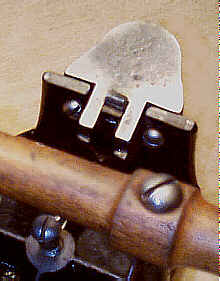
The plane has "No. 11 1/2" embossed on the extension
piece,
withing the familiar Stanley notched rectangle. The #11's main casting was used for
this plane. The #11 has its number cast
at its toe. For the #11 1/2, the
#11 casting
number is ground off and then filled with a glob of
japanning. Don't ever buy
an example that has "No. 11" cast into the main casting
and "No.
#11 1/2" cast into the extension piece - it's a monkey,
made up from two
different planes. Also, check the japanning very carefully
where the #11 is ground off. It's
very easy for a crafty 'artist' to practice plane forgery
on these planes where
the plane is converted long after it left the factory.
The iron is normally stamped with the Stanley
trademark on both sides; the
plane beds the iron bevel up, and with the normal iron the
logo would be face
down, thus the reason for stamping the logo on the beveled
side of the iron.
Stanley wanted make it certain that the members of the
floorplaners' union knew
exactly who was using their product.
Be sure to inspect the adjusting mechanism of this
tool as floorplaning was
a rugged task. A snapped adjusting yoke, cracks at the back
of the main
casting, and missing chunks of the main casting are the
major problems with the
tool.
The plane was used in the kneeling position (kneeling
before a false God?)
and is pulled toward you. Ask yourself this question - you
really want one of
these to use? Instead, floor sandahs (sander, in New
England-ese) are so much
more stimulating. Leave this one for the diehard Stanley
junkies as it's a much
scarcer plane than one might think.
[ START ] |
[ PREV ] | [ NEXT
] | [ END ]
[ HOME
]
Copyright
(c) 1998-2012 by Patrick A. Leach. All Rights Reserved.
No part may be
reproduced by any means without the express written
permission of the author.