The Superior Works: Patrick's Blood and Gore Planes #12 - #20 1/2
Quick Find: #12, #12 1/4, #12 1/2, #12 3/4, #13, #14, #15, #15 1/2, #16, #17, #18, #A18, #S18, #18 1/4, #19, #20, #20 1/2
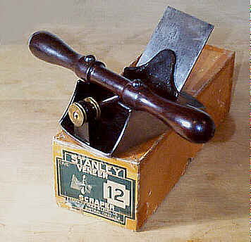
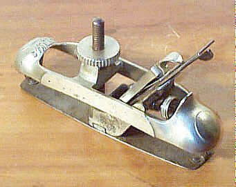
#12 Veneer scraper, 6 1/4"L, 3"W (2 7/8"W 1925 on), 3 3/4lbs, 1870-1947.
 This
is the most common of
Stanley's adjustable scrapers. A latter day manufacturer,
from Germany, made
pitiful copies of this plane, characterized by low-rate
castings smeared with a
hideous green paint.
This
is the most common of
Stanley's adjustable scrapers. A latter day manufacturer,
from Germany, made
pitiful copies of this plane, characterized by low-rate
castings smeared with a
hideous green paint.
If you plan to do a lot of scraping, these are nice
to own since they save
your fingers from getting burned (due to the friction
between the scraper and
the wood). They also prevent the edges of the blade from
digging into the wood,
which is apt to happen on softer woods. They do not bow the
blade a bit, like
the #80 does,
since these tools are more properly scraper planes than
they are scraper
holders. These also make great paint scrapers.
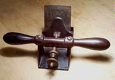
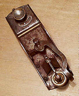
A regular scraper blade, made of softer steel so that
its edge can be rolled
over, is held in an adjustable (pitch) holder. The holder
consists of a captive
lever cap, which is fastened to another casting that pivots
at its bottom,
located above the tool's mouth. Together, these two castings
receive and
sandwich the blade, and hold it in place by turning a brass
clamping screw
through the lever cap proper. The two castings are attached
to the main casting
with a rod that is visible from, and ground flush to, the
sides of the tool.
The rod is driven into the main casting from one direction
only so if you have
to drive it out, and it's not budging, flip it over and
drive it from the other
side.
The blade clamping assembly is, in turn, connected to
a long, partially
threaded rod, which projects nearly perpendicular to the
clamping assembly.
This rod pierces a raised rectangular portion of the main
casting, and carries
two brass nuts that sandwich this portion. Together, the two
nuts are adjusted
to regulate the blade's pitch. The blade can be pitched
roughly from 45 degrees
to 95 degrees, making the tool particularly useful and
customizable for
stubborn wood grains. In addition to regulating the pitch of
the blade, the two
brass nuts also permit the fine adjustment of the blade's
set; the blade can be
pitched forward for a deeper set, and backward for a finer
set. The identical
blade holding/adjustment assembly is found on the #12
1/4, #12
1/2, #12
3/4, #112, and #212.
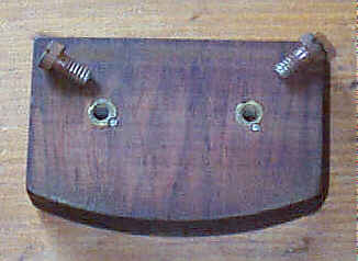
There is a nicely turned rosewood handle that is
screwed crosswise to the
scraper. It provides a comfortable grip for the workman to
bear down on the
tool when working it. Toothing blades can also be used to
prepare the surface
for preliminary surfacing or veneering. Original Stanley
toothing blades are
quite scarce, and can sometimes cost more than this tool
does. The toothing
cutters came in 22, 28, and 32 teeth per inch.
There's not really much to be watchful over as far as
damage is concerned on
these tools other than chips or cracks in the castings,
which any iron tool can
suffer. I have noticed a few examples that have suffered a
rather unusual flaw
- they have breakage about the lower portion of the blade
clamping castings.
This damage is easy to note by looking at the casting
through the tool's mouth.
The casting completely houses a rod, which allows it to
pivot. If you can see
the pin, the casting is broken. Also check the blade
clamping assembly, where
the two castings join each other, for any breakage or
repairs; the area that
permits the lever cap to pivot can sometimes be found
cracked or repaired.
Where the threaded rod is pinned to the blade clamping
assembly can also
sometimes be broken or repaired. Other than this damage, the
tools seem to be
tough little monkeys overall.
There are no holes drilled in the rosewood handle or
sole. If you see any,
it's been modified. Surprisingly, many guys would tap holes
into the main
casting so that they could attach a wooden sole. Perhaps
they lusted after the #12 1/2, after they
bought their #12's, but their
frugality prevented them from succumbing to Stanley's
lastest and greatest
scraper offerings.
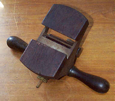
 The earlier model has
its
toe and heel cast so that they are both straight across the
width of the bottom
casting. The later model has both slightly arched convex
across the width. The
outermost brass adjusting nut can be found with the patent
date on the earliest
models as well as some later ones - Stanley must have had an
ample supply of
these nuts so marked. However, the earliest nuts are stamped
"L.BAILEY" over "PATENT / AUG. 31 - 58". Furthermore, the
early model does not have "No 12" cast into it, whereas the
later
model does. Other than this subtle modification, the tool
never underwent any
modification. It worked right from the start, and didn't
need any enhancements
or tweaking, which seemed to be standard operating procedure
for many other
Stanley tools.
The earlier model has
its
toe and heel cast so that they are both straight across the
width of the bottom
casting. The later model has both slightly arched convex
across the width. The
outermost brass adjusting nut can be found with the patent
date on the earliest
models as well as some later ones - Stanley must have had an
ample supply of
these nuts so marked. However, the earliest nuts are stamped
"L.BAILEY" over "PATENT / AUG. 31 - 58". Furthermore, the
early model does not have "No 12" cast into it, whereas the
later
model does. Other than this subtle modification, the tool
never underwent any
modification. It worked right from the start, and didn't
need any enhancements
or tweaking, which seemed to be standard operating procedure
for many other
Stanley tools.
Some folks are at first confused about how the blade
should be oriented in
the tool. Just make sure that the hooked edge of the blade
faces away from the
two brass nuts that adjust the holder; the hook is on the
same side as the
brass clamping screw. To protect the burr, you should always
insert the blade
from the sole as it's possible to catch the burr on the
relatively narrow
opening through the clamping assembly.
Place the tool on a flat surface, after the blade had
been inserted, and let
the hooked edge make contact with the surface (you can slip
a piece of paper
under the portion of the sole, toward which the hook faces,
to start with a
very fine set). Back the inner brass nut off just a bit, and
then turn the
outer one so that it's tight. This tiny adjustment will
pitch the cutter
backward ever so slightly, which in turn raises the hooked
edge of the blade
thereby decreasing the depth of cut. If the tool doesn't
cut, you'll need to
pitch the blade the other way to increase the blade's set by
pitching the blade
forward. To pitch the blade forward, back the outermost
brass nut off and turn
the inner nut so that it's tight against the raised portion
of the main casting
that the two nuts sandwich.
Grip both ends of the turned handle with each hand,
with the two brass
adjusting screws oriented toward your body. Place the plane
on the wood, with
your body directly behind it. Pressing it firmly downward,
push it away from
your body, and watch 3" wide shaving curl from the wood.
Place the
shavings in a jar, take them into work, and amaze your pals
during
deipnosophistic lunchtime banter. Folks will dig you
bigtime!
If you find that the tool skips over the wood's
surface, you may want to
decrease the set just a bit, but before doing that be sure
that you're placing
sufficient pressure on the tool's toe. You can do this by
extending both your
first fingers forward and placing them on the main casting,
before the blade.
Rolling your wrists forward just a bit will place some force
on your fingers
which in turn puts increased pressure on the toe.
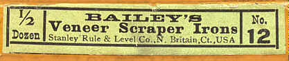 Finding original blades
for these tools, and all of the scrapers that make use of
the same adjusting
assembly, can be tough. Because of the tool's design, most
of the blade is
unusable, so any that were subjected to a lot of scraping
went through blades
rather quickly. Most of the tools are found without their
original blades, or,
if they have them, the blades are nearly too short to use.
Save the original
blades and locate a suitable replacement. Some sort of
Stanley logo can be
found on the blades, but some of them were never marked.
Finding original blades
for these tools, and all of the scrapers that make use of
the same adjusting
assembly, can be tough. Because of the tool's design, most
of the blade is
unusable, so any that were subjected to a lot of scraping
went through blades
rather quickly. Most of the tools are found without their
original blades, or,
if they have them, the blades are nearly too short to use.
Save the original
blades and locate a suitable replacement. Some sort of
Stanley logo can be
found on the blades, but some of them were never marked.
#12 1/4 Veneer scraper, 6 1/4"L, 2"W, 2 1/2lbs, 1912-1941. *
This is the narrower version of the #12 (identical in all other regards), and was designed for lighter work. If you ever find a #12 1/4 missing its handle, or one with a broken handle, don't go thinking you can replace it with one from a #12 or #12 1/2. They won't fit since the screw holes that are drilled through them are too far apart for the narrower #12 1/4. These scrapers are definitely less numerous than their larger brothers.
#12 1/2 Veneer scraper, 6 1/4"L, 3"W (2 7/8"W 1925 on), 4lbs, 1905-1943.
 Same
as the #12, except that the sole of the
scraper has a piece of
3/8" rosewood screwed to it. This supposedly helped to
minimize marring or
scratching the wood's surface. Many examples have their
original rosewood sole
all beat to hell from use. Things like gouges, splintered
sections, uneven
wear, and screws poking through the wood are typical
problems the sole suffers.
You can replace the sole with a hardwood of your choice
rather easily.
Same
as the #12, except that the sole of the
scraper has a piece of
3/8" rosewood screwed to it. This supposedly helped to
minimize marring or
scratching the wood's surface. Many examples have their
original rosewood sole
all beat to hell from use. Things like gouges, splintered
sections, uneven
wear, and screws poking through the wood are typical
problems the sole suffers.
You can replace the sole with a hardwood of your choice
rather easily.
Occasionally, a #12 will surface that's been modified to resemble
this plane. However,
it's very easy to distinguish between the two models,
despite the exact
dimensions they share. First, this model has the number
"No 12 1/2"
cast into the bottom casting. Second, there are four
regularly spaced screw
holes - two forward of the blade and two behind the blade
- through the bottom
casting. The holes are not threaded and allow the passage
of round-headed
screws into the rosewood sole. Third, the mouth of the
main casting is wider
than that found on the #12. Fourth, the blade clamping
assembly is longer by
about 1/4" on the #12 1/2
than it is on #12. In fact, some of the clamping assemblies on the
#12 1/2 have
"12 1/2" crudely incised in the
assembly, just below where the threaded rod attaches to
it. The reason for the
assembly being a bit longer on this plane is because of
the rosewood sole. Its
thickness would make the blade flex too much when the
plane is in use were it
the same length assembly as that used on the #12.
#12 3/4 Scraper plane, 6 1/4"L, 2 7/8"W, 3 1/2 lbs, 1930-1943. *
 This beast
looks
just like the #12
and #12 1/2,
except it has two massive blocks of rosewood attached to
its sole - one forward
of the blade and one behind the blade. This feature
supposedly offered greater
spring to the blade since there is a greater amount of
blade left unsupported.
This beast
looks
just like the #12
and #12 1/2,
except it has two massive blocks of rosewood attached to
its sole - one forward
of the blade and one behind the blade. This feature
supposedly offered greater
spring to the blade since there is a greater amount of
blade left unsupported.
Stanley's tool propaganda stated that the rosewood
blocks were oriented to
the tool so that the screws entered the endgrain. One
example of this plane
with the grain oriented as advertised is extant. However,
all other specimens
have the grain running parallel to the tool's sole so that
the screws enter the
long grain.
The two rosewood blocks, each 13/16" thick, are
identical to each other
in size and shape. The ends of the blocks, where they are
adjacent to the
tool's mouth, are cut on a bevel so that the bevel slopes
down toward the sole;
i.e., when viewed from the side, the blocks form what looks
like a dovetail,
with the widest portion of the dovetail up against the
casting. The beveled
edge of each block is very crudely finished, with telltale
remnants of the sawing
clearly visible. Examples can be noted where the blocks of
rosewood are not
perfectly aligned with the main casting.
This plane is very rare, and is very easy to pass off
as legitimate to the
unsuspecting Stanley plane collector. The number is not cast
into the plane. A
regular #12 1/2
bottom casting is used, and the number "No 12 1/2" will be
found cast
onto the plane. The tool's mouth is a full 1" wide,
whereas the other ones
of this series have mouths about 3/8" wide.
 The
rosewood
blocks are held to the main casting via screws, as the #12
1/2 does.
However, the screws used on
the #12 3/4
differ from those
used on the #12 1/2. The former uses flat-headed screws while the
latter uses round-headed
ones. Now here's something not many guys know - the screws
are the same
(thread, length, and head diameter) as those used on the
Bailey bench planes.
Ain't it amazing what information is contained within
Blood & Gore? Now
you're an instant expert, or maybe you just look like one,
without your having
sent away for a tool diploma offered by some matchbook
cover correspondance
school.
The
rosewood
blocks are held to the main casting via screws, as the #12
1/2 does.
However, the screws used on
the #12 3/4
differ from those
used on the #12 1/2. The former uses flat-headed screws while the
latter uses round-headed
ones. Now here's something not many guys know - the screws
are the same
(thread, length, and head diameter) as those used on the
Bailey bench planes.
Ain't it amazing what information is contained within
Blood & Gore? Now
you're an instant expert, or maybe you just look like one,
without your having
sent away for a tool diploma offered by some matchbook
cover correspondance
school.
The screws do not screw into the wood directly, but
into brass bushings,
which are pinned into the wood in the same manner that was
used on the
transitional bench planes. This feature cannot be seen
unless the wood is
removed from the main casting.
There are fake examples of this plane out in old tool
land. Many can be
traced to the northeast of USofA. To the unsuspecting eye,
the fakes are very
good. There is, however, one thing that the forger didn't do
well - he/she/it
failed to bore the holes vertically into the wood. Look very
carefully at how
the screws are oriented - they should sit flush on the main
casting. If they
lean at all, even to the point of leaning away from each
other, it's likely a
forgery. Also, the bushings used on the fakes are a larger
diameter than the
originals.
This plane is one of the rarest of Stanley tools, and
is better left to the
diehard collectors of them.
#13 Circular plane, 10 1/2"L, 1 3/4"W, 3lbs, 1871-1909.
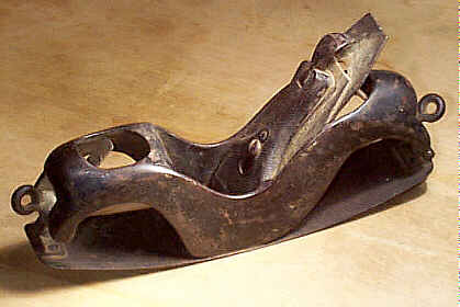 This
is Leonard Bailey's design
for a circular plane. It has a flexible steel sole which can
be made concave or
convex by manually bending it. Circular planes are used to
plane curved
sections, like rockers, wheels, stair parts, for
boatbuilding, etc.
This
is Leonard Bailey's design
for a circular plane. It has a flexible steel sole which can
be made concave or
convex by manually bending it. Circular planes are used to
plane curved
sections, like rockers, wheels, stair parts, for
boatbuilding, etc.
Two thumb screws, each with an eye to accommodate a
nail or something
similar, are tightened against their respective adjusting
strap - one forward
of the iron and one rearward of the iron - to secure the
sole in position.
These adjusting straps are hinged to the sole. Look about
the hinges for any
signs of tears or repairs.
The "frog" is permanently secured to the main casting
with four
round-headed screws. And while on the topic of screws, the
common earlier
models have the sole fastened to the plane with screws. On
some examples,
repeated use breaks the sole around the screws. A change to
the fastening
method was made to solve this - it is a dovetailed piece
from the sole to the
body. Even these break, so check them. The linkages on the
front and back of
the sole, which allow the sole to flex, also are prone to
breakage.
The very first models of this plane, manufactured by
Leonard Bailey while
still doing the Boston scene, are rare. They have wing nuts
that lock the sole
into position. The sole does not have the hinges that link
the straps to the
sole. In fact, the straps and sole are one piece, with the
straps bent upward
and split so that the sole tightening screw can fit through
them. This design
proved very fragile as the sole was prone to ripping where
the straps join.
The plane has the patented Bailey features.
Initially, the plane did not
have the lateral adjustment lever, but it was soon added
once the feature made
it on the bench planes. A large number of these planes can
be found with the
solid adjusting nut and no lateral adjustment lever. The
sales of the
mechanically adjustable models probably account for this as
they cut into the
sales of this model once the mechanical ones made their
debut. Prior to the
mechanical ones, all circular planes were manually
adjustable. The plane
carries the same textured lever cap found on the
transitional planes (see that
section for an image).
An early catalog reference stated that the plane
could work an inside circle
of 12 1/2 inches and on outside circle of 18 1/2 inches. The
outer diameter
couldn't be as small as the inner since there would be a
severe amount of
strain put on the sole and because the adjusting straps
can't swing through the
same range due to the main casting.
These circular planes aren't nearly as easy to use as
the #20 and #113 for the fact that the sole isn't adjusted by
mechanical means. To get
a fair curvature to the bottom, you have to adjust the
front portion and rear
portion of the sold independently from each other and hope
that you give them
the same radius. You can cut a template of the required
radius and then set the
plane's sole from that.
These planes don't command as much money as Stanley's
other circular planes
because of their primitive sole adjustment. If you're on a
tool budget, imposed
upon you by a stingy housemate, you might want to consider
this one for your
arsenal. But, you'll never claim bragging rights with the
big boys, who have
firm control over the household finances, when buying this
one.
#14 Cheese Plane, 1066BC-2001AD.
hohoho! There is no #14. Why? Who knows. This is the first break in the numbering sequence, and the reason for it went to the grave with all them old Stanley employees. There are more breaks in the numbering sequence.
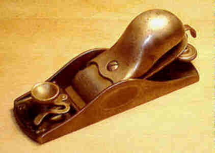
#15 Block plane, 7"L, 1 3/4"W (1 5/8"W 1909 on), 1 5/8lbs, 1876-1955.
 This plane is identical
to the #9 1/2
except for its length and weight.
This plane is identical
to the #9 1/2
except for its length and weight.
This plane was offered a few years after the #9 1/2 and thus cannot be found in
the similar earliest
configurations as the #9
1/2. However,
once the plane was put into production,
it pretty much paralleled the improvements and
modifications made to the #9
1/2.
The #15
pictured here shows the
characteristic Excelsior design, where the hump of the
side wall is noticeably
toward the rear of the plane to give it a more aerodynamic
look (it is a plane,
afterall). This casting was used on the plane from its
inception and was
dropped ca. 1900 when the hump was located right in the
middle of the plane.
Although it isn't visible in the image, this
particular #15 has
the fanciful Bailey and patent date etching on
the left cheek (the same style of etching was commonly
used on handsaws). It is
the only #15 to have surfaced
with this etching, which up until now was only found on a
few contemporary
models of the #9 1/2. The lever caps on these
planes show the gothic
arch pattern at the leading edge of the lever cap.
#15 1/2 Block plane, 7"L, 1 3/4"W (1 5/8"W 1909 on), 1 5/8lbs, 1876-1934. *
This plane is identical to the #9 3/4 except for its length and weight. The rear handle used on this plane is identical to that used on the #9 3/4.
Pay close attention to the threads, if you're looking for
a replacement
locking nut for the rear handle.
#16 Block plane, 6"L, 1 3/4"W (1 5/8"W 1909 on), 1 1/2lbs, 1888-1941.
This plane is identical to the #9 1/2 except that its metal trim is nickel plated; the front knob, the depth adjustment nut, and the lever cap are nickel plated.
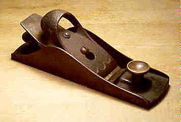
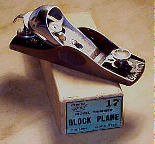
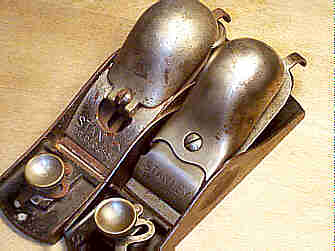
#17 Block plane, 7"L, 1 3/4"W (1 5/8"W 1909 on), 1 5/8lbs, 1888-1941.
 This plane is identical
to the #15 except
that its metal trim is nickel plated, just like the #16's trim is. You can sometimes
find the plane marked
with its number stamped into the lateral adjuster, where
it bends downward at
the end you grip. It's a rather strange place to find the
plane's marking as
the lateral adjuster is common amongst all the adjustable
20 degree block
planes. The #19 is also sometimes marked on the adjuster.
This plane is identical
to the #15 except
that its metal trim is nickel plated, just like the #16's trim is. You can sometimes
find the plane marked
with its number stamped into the lateral adjuster, where
it bends downward at
the end you grip. It's a rather strange place to find the
plane's marking as
the lateral adjuster is common amongst all the adjustable
20 degree block
planes. The #19 is also sometimes marked on the adjuster.
The #17
pictured here is stamped on its
left side "IMPERFECT" because there is a tiny, pin-head
sized pock
mark in the main casting, which couldn't be machined out
of the casting without
compromising its strength. The plane is otherwise
flawless, and received all
the proper machining and finish trim that a perfect
example got.
The cutter is marked with the sweetheart logo, dating
this plane to the
early 1920's. Stanley sold these planes to cut-rate hardware
stores, but the
boxes they shipped them in do not make any mention of the
manufacturer. The
label for this plane just lists the model number, what the
plane's function is,
and its dimensions.
Prior to around this date, Stanley simply trashed the
castings that had
imperfections, which weren't discovered until after
machining. However, as the
cost of labor increased, and the effort spent to find out
later that the tool
would be 'imperfect', the work already done actually cost
the company real
money. Stanley decided to recoup as much cost as possible by
simply finishing
the tool, only to sell it at a slimmer profit than they
would have realized had
the tool been flawless. Perhaps this business modus operandi
is the begining of
the downhill slide in tool quality that we now suffer when
shopping at Home
Cheapo outlets?
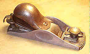
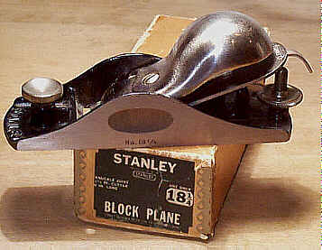
#18 Block plane, 6"L, 1 3/4"W (1 5/8"W 1909 on), 1 1/2lbs, 1888-1950.
 Yet
another block plane! Like all
the others listed so far, but with one distinguishing
feature - a knuckle joint
lever cap. So, what's this knuckle joint lever cap anyway?
It, in my opinion,
is one of the coolest contraptions ever to leave New
Britain. The second design
of the lever cap, that is.
Yet
another block plane! Like all
the others listed so far, but with one distinguishing
feature - a knuckle joint
lever cap. So, what's this knuckle joint lever cap anyway?
It, in my opinion,
is one of the coolest contraptions ever to leave New
Britain. The second design
of the lever cap, that is.
The knuckle joint cap is a two-piece pressed steel
cap that has a
comfortable palm rest, which snaps a linkage to place
pressure on what is the
lever cap proper. A good approximation of what the knuckle
joint lever cap
looks like is a conventional bench plane's lever cap with a
spoon, concave
portion downward, resting over a good length of the lever
cap, pinned crosswise
to the lever cap. The 'spoon' portion of the lever cap,
then, is oriented
upward, and fits into the palm, making for good, sure grip
of the plane during
use.
The 'spoon' portion lifts up and down, loosening or
snapping the lever cap
in place, as the case may be; raising it takes the pressure
off the cutter
while lowering it locks it. Because of the way the lever cap
is activated,
there is little chance that the iron can be knocked out of
lateral truth like
it can be with the conventional block plane lever cap, which
relies on a small
lever that's activated by rotating it. This design proved to
be very effective,
barring a minor design flaw during its introduction. The
flaw was soon
corrected.
 The first release of
the
knuckle joint relied on a two-prong fork-like piece that
engaged the lever cap
screw, which protrudes above the iron, at the leverage point
of the cap. These
lever caps have "PAT. DEC.28.86." stamped along its lower
edge. It
wasn't a very good design, since many of the caps broke
about this point,
rendering the plane useless. The cap never really locks into
place all that
well, and can often pop free during use. Apart from the
forks on the cap, the
early-style cap can easily be distinguished from the
improved design by the
number of parts it has - the early one only has a two-part
cap.
The first release of
the
knuckle joint relied on a two-prong fork-like piece that
engaged the lever cap
screw, which protrudes above the iron, at the leverage point
of the cap. These
lever caps have "PAT. DEC.28.86." stamped along its lower
edge. It
wasn't a very good design, since many of the caps broke
about this point,
rendering the plane useless. The cap never really locks into
place all that
well, and can often pop free during use. Apart from the
forks on the cap, the
early-style cap can easily be distinguished from the
improved design by the
number of parts it has - the early one only has a two-part
cap.
The cap was redesigned to overcome the flaws of the
earlier design. The
solution was to make a conventional-style lever cap slip
over the lever cap
screw, and through the means of a two-piece linkage, the
'spoon' portion of the
lever cap places pressure on the iron when it's snapped in
place. This new
design of the lever cap is made up of 4 pieces, and it's the
one you should
look for, if you plan to use the plane.
Check that this newer mechanism functions well, and
that the linkages under
the lever cap are proper are sound. I have seen cracked
examples of the lever
cap, making thorough scrutinization mandatory. The lever
caps came nickel
plated, but they are often found with a lot of it missing
from years of use.
However, a surprising amount of it can often be found on the
lever cap.
Check the sole, just behind the iron, very carefully
on these planes.
Because the knuckle joint lever cap can exert a great amount
of force on the
iron, due to its design, the sole can develop stress cracks
to either side of
the back of the mouth. Also, make sure that the lever cap
screw is proper for
the plane. The lever cap screw on planes originally equipped
with the knuckle
joint lever cap are a bit longer than those used on the
other block planes.
Some guys will take a #9 1/2 and pop a knuckle joint lever
cap on it. If this is
done, the lever cap screw must be backed off to
accommodate the lever cap. This
results in fewer threads holding the lever cap screw to
the main casting.
Oh yeah, this plane is like the #16, which is like the #9
1/2,
in every way except for the
knuckle joint cap. In other words, it has the adjustable
mouth, the lateral
adjustment lever, and the brass depth adjusting nut.
#A18 Block plane, 6"L, 1 5/8"W, 7/8lbs, 1925-1934. *
 The aluminum version of
the #18. Imagine
just how lucky you are saving a total of 5/8lb. using one
of these over a
standard #18.
ZOWEE! They didn't sell like hotcakes despite the obvious
benefit of giving
your arm the rest it needs by reducing the weight of your
tool. Like the #18, all the trimmings
of this planes are nickel plated, which is usually long
gone on the specimens
that surface.
The aluminum version of
the #18. Imagine
just how lucky you are saving a total of 5/8lb. using one
of these over a
standard #18.
ZOWEE! They didn't sell like hotcakes despite the obvious
benefit of giving
your arm the rest it needs by reducing the weight of your
tool. Like the #18, all the trimmings
of this planes are nickel plated, which is usually long
gone on the specimens
that surface.
Like all the aluminum planes, these things can become
pretty heinous looking
after 2 hours of use. Those that haven't been used are sorta
neat looking
bearing a striking resemblance to a Daredevil, Jitterbug,
Hullapopper, etc.
fishing lure. Good thing they don't come equipped with a
treble hook otherwise
you may be taken hook, line, and sinker by one of these
wonders of the tool
world.
#S18 Block plane, 6"L, 1 5/8"W, 1 1/8lbs, 1925-1941
 This is the
indestruct-o-version of the #18, made of a pressed steel body
like that used on the
#S4 and #S5. Stanley had a
concept going with aluminum and steel, and they were
obsessed to apply it to as
many planes as they could in their attempt to make the
mundane extraordinary
when in reality they actually made the bland blander.
Luckily, a World War
popped up at just the right time to KO this pitiful
product that Stanley tried
to jazz up by nickel plating the lever cap, knob, and
cutter adjuster.
This is the
indestruct-o-version of the #18, made of a pressed steel body
like that used on the
#S4 and #S5. Stanley had a
concept going with aluminum and steel, and they were
obsessed to apply it to as
many planes as they could in their attempt to make the
mundane extraordinary
when in reality they actually made the bland blander.
Luckily, a World War
popped up at just the right time to KO this pitiful
product that Stanley tried
to jazz up by nickel plating the lever cap, knob, and
cutter adjuster.
The plane's steel body, with a japanned interior, has
two circular cutouts
along the arched sides in this plane's version of the Hand-y
grip (the lengths
Stanley would go to make something different, yet the same,
are mind-numbing).
The lateral adjustment lever screws into a rivetted
two-piece, I-beam shaped
cross member that is itself rivetted to the sides of the
plane's body. The
cutter's depth adjustment lever is pinned to another
rivetted two-piece
construction that's also rivetted to the body. One look at
the plane and you'll
quickly see that the thing must have been engineered by an
unemployed
ironworker; cockroaches will have good company in the event
of a nuclear
holocaust.
 The plane has an
adjustable mouth that's similar to that used on the #18, but it's different. The
sliding section (to close
the mouth) isn't fit into the sole, but sits atop the
body. The section is bent
down into the mouth, and it's this bent section that moves
nearer/farther from
the cutter. As a result of this design, a gap in the sole
forms when the mouth
is closed. This gap can become jammed up with wood schmutz
causing the plane to
lift ever so slightly away from the wood, which, as any
Einstein quickly
realizes, will make the plane stop cutting, especially
when the mouth is set
fine. The model number, "No S18", is stamped into the toe
of the
sliding section, just in case you have a tough time
distinguishing cast iron
from pressed steel, I suppose.
The plane has an
adjustable mouth that's similar to that used on the #18, but it's different. The
sliding section (to close
the mouth) isn't fit into the sole, but sits atop the
body. The section is bent
down into the mouth, and it's this bent section that moves
nearer/farther from
the cutter. As a result of this design, a gap in the sole
forms when the mouth
is closed. This gap can become jammed up with wood schmutz
causing the plane to
lift ever so slightly away from the wood, which, as any
Einstein quickly
realizes, will make the plane stop cutting, especially
when the mouth is set
fine. The model number, "No S18", is stamped into the toe
of the
sliding section, just in case you have a tough time
distinguishing cast iron
from pressed steel, I suppose.
The sliding section uses an eccentric cam that's
unique to this plane. The
cam pivots directly below the knob with the arc-shaped slot
swinging over a
small, projecting pin that's peened onto the sliding
section. I find that this
design works smoother than that used on the rest of the #9 1/2 family
of block planes. This design is the only redeeming thing
that can be said about
this ugly little monster, which is what they normally look
like after a few
hours use, in my not so humble opinion.
Go ahead. Buy this plane, then slam it into whatever
mass of concrete is
convenient. See if it bounces back and begs for more. I dare
you. Double dare
you.
#18 1/4 Block plane, 6"L, 1 5/8"W, 1 1/2lbs, 1952-1958. *
 Another stupid block
plane! Like the #9 1/4 with its non-adjustable mouth, but with the same
knuckle-joint lever
cap like that found on the #18. Do you see a trend developing
here? Stanley musta
kicked themselves in the butt for not offering this one
earlier, but better
late than never was the master plan back then. However,
this time, it was too
late to take advantage of Joe Meatball's spendy way by
selling him another
block plane. By this time, he got smart and bought
'lectrical tools.
Another stupid block
plane! Like the #9 1/4 with its non-adjustable mouth, but with the same
knuckle-joint lever
cap like that found on the #18. Do you see a trend developing
here? Stanley musta
kicked themselves in the butt for not offering this one
earlier, but better
late than never was the master plan back then. However,
this time, it was too
late to take advantage of Joe Meatball's spendy way by
selling him another
block plane. By this time, he got smart and bought
'lectrical tools.
These are rather scarce, and it's easy to take a
common #9 1/4 and pop a
knuckle-joint lever cap on it to fool the rookie tool
collector. All of the
proper #18 1/4's have the number
stamped into the left side of the main casting, down near
the sole, below the
Hand-Y grip. The #18 1/4 also
has nickel trimming; i.e., the knob, the lever cap, and
the adjuster are all
nickel plated. There you have it - you're now an instant
expert at #18
1/4 identification.
The example pictured here comes in its original box
that has the metal
corners, which were all the rage on Stanley's boxes from the
mid-1950's onward.
The metal corners were added to keep the box's corners from
splitting apart,
which must have pissed off all the guys what stored their
tools in their
original boxes. Generally, boxes make a tool worth
considerably more than it
otherwise is. However, the metal corners are not that
popular with collectors,
but in the case of this particular plane they are ok since
the plane didn't
make its debut until the time metal corners were appearing.
#19 Block plane, 7"L, 1 5/8"W, 1 5/8lbs, 1888-1949.
Hoo boy! Same as the #18, except that this one is an inch longer.
I have noticed on some examples of this plane that
the model number,
"No. 19" is stamped into the lateral adjustment lever. This
is very
unusual since model numbers were generally cast into the
planes in an obvious
place, when Stanley felt like marking their block planes
(which they typically
did by stamping the number below the left Hand-y grip, on
the planes with the
full adjustment mechanisms).
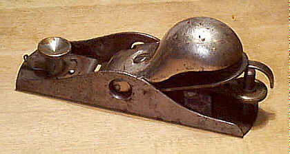
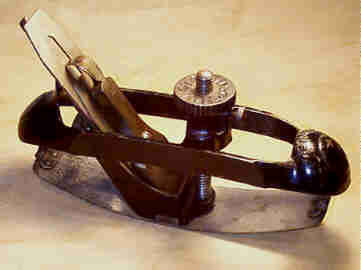
#20 Victor circular plane, 9 1/2"L (10"L 1912 on), 1 3/4"W, 4lbs, 1880-1958.
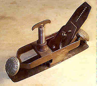 This is Leonard
Bailey's design, of the style that he patented after he sold
his original patents
to Stanley back in 1869 (Bailey got pissed at Stanley so he
decided to make
another line, which he eventually sold to Stanley, again,
but that's another
bedtime story for another night). This is the only plane of
the Victor line
that was continued by Stanley for any length of time after
they bought Bailey
out the second time.
This is Leonard
Bailey's design, of the style that he patented after he sold
his original patents
to Stanley back in 1869 (Bailey got pissed at Stanley so he
decided to make
another line, which he eventually sold to Stanley, again,
but that's another
bedtime story for another night). This is the only plane of
the Victor line
that was continued by Stanley for any length of time after
they bought Bailey
out the second time.
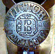
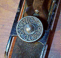
The earliest models (Leonard Bailey's Victor) have
two large cast and nickel
plated medallions screwed (from behind) to the plane's
pressed steel frame -
one at the toe and one at the heel. Both the medallions are
identical, and have
"VICTOR TRADE LB MARK PLANE" embossed and incised in them.
The
medallions are often missing, but reproduction ones were
once being
manufactured (they don't have the fine detail that the
originals do). The iron
has the Victor line's characteristic "perforated" iron,
where a
series of holes are arranged linearly to fit into a pin
carried by an adjusting
arm. This adjusting arm is activated by turning a knurled
disk located behind
and at the top of the frog. This early plane looks sorta
futuristic for the
time it was manufactured, and the early model of this plane
is much more
valuable than the more common configuration, but only when
it's complete with
its original parts.
 The plane
underwent a substantial re-design just before 1900, and the
Victor style of
iron adjustment was dropped for the conventional Bailey
style. Most of these
planes will have "PAT'D 2-7-93" cast into the main casting
to either
side of the adjusting wheel, and have "VICTOR No. 20" cast
into the
adjusting wheel.
The plane
underwent a substantial re-design just before 1900, and the
Victor style of
iron adjustment was dropped for the conventional Bailey
style. Most of these
planes will have "PAT'D 2-7-93" cast into the main casting
to either
side of the adjusting wheel, and have "VICTOR No. 20" cast
into the
adjusting wheel.
The first Stanley production model does not have the
patent information
embossed in the plane, nor does it mention Victor on it
anywhere. Instead, it
just has "No. 20 STANLEY" embossed at the toe of the plane
(see the
image of the nickel plated example below for the type 1
Stanley production).
The dovetail on the sole (where it slips into the frog) is
stamped with its
patent date of June 17, 79 (the same sole attachment patent
as that used on the
#113).
The cap iron will have "PAT FEB 7 '93/PATENT APLd. FOR"
stamped into
them (these are very tough to find).
The winged thumbscrew, found on the Bailey Victor
model of the plane, which
adjusts the curvature of the sole was re-designed to be a
captive wheel that is
aligned parallel to the plane's sole. Look around the where
the wheel slips
into the main casting for any sign of cracks, missing chunks
of cast iron, or
repairs.
 The later models also
dropped the decorative medallions, and the frame was cast
from iron, instead of
made from two steel strips fastened together as done on the
earliest ones. This
frame can crack anywhere along its sides, but is most often
cracked, or
downright broken, on the two housings that join the sole
linkages to the
flexible sole. It's misleading to claim that this is a
common problem, but I
have noted several that are broken here. The rails of the
plane are also prone
to cracking so give them a close inspection - it's possible
to find breakages
here repaired with plates riveted to the rails. Look
carefully on the inside of
the main casting for any signs of welding. The casting that
carries the blade
adjusting mechanisms can also be damaged where the sole is
dovetailed into it.
Look for any stress cracks around the dovetail, especially
about the forward
area of the dovetail.
The later models also
dropped the decorative medallions, and the frame was cast
from iron, instead of
made from two steel strips fastened together as done on the
earliest ones. This
frame can crack anywhere along its sides, but is most often
cracked, or
downright broken, on the two housings that join the sole
linkages to the
flexible sole. It's misleading to claim that this is a
common problem, but I
have noted several that are broken here. The rails of the
plane are also prone
to cracking so give them a close inspection - it's possible
to find breakages
here repaired with plates riveted to the rails. Look
carefully on the inside of
the main casting for any signs of welding. The casting that
carries the blade
adjusting mechanisms can also be damaged where the sole is
dovetailed into it.
Look for any stress cracks around the dovetail, especially
about the forward
area of the dovetail.
 The sole linkages can
have the same problems that are explained for the #13. This plane has a frog design
unique to it, and if
yours is broken, you'll need to locate a suitable
replacement instead of
lifting one from a broken #3. Also, the cap iron is unique
to this plane - the
slot that engages the adjustment fork is situated nearer
to the top of the cap
iron than it is on the bench planes. Be sure to check the
iron's depth
adjustment range to verify that the cap iron is correct,
otherwise you'll be
left with a plane that can only accommodate a very fine
set. Check that the
small thumb screw, below the adjusting wheel, that locks
the sole's adjustment
in place is a finely knurled one and not slotted. Many of
these thumb screws
are replaced.
The sole linkages can
have the same problems that are explained for the #13. This plane has a frog design
unique to it, and if
yours is broken, you'll need to locate a suitable
replacement instead of
lifting one from a broken #3. Also, the cap iron is unique
to this plane - the
slot that engages the adjustment fork is situated nearer
to the top of the cap
iron than it is on the bench planes. Be sure to check the
iron's depth
adjustment range to verify that the cap iron is correct,
otherwise you'll be
left with a plane that can only accommodate a very fine
set. Check that the
small thumb screw, below the adjusting wheel, that locks
the sole's adjustment
in place is a finely knurled one and not slotted. Many of
these thumb screws
are replaced.
These planes have full nickel plating, and when they
are in mint condition,
are very striking in appearance. Be sure that the frog, the
lever cap, the depth
adjustment nut, and the lateral lever are all nickel plated.
If they aren't,
they've been replaced. Full nickel plating proved to be too
costly, and the
nickel plating was dropped ca. 1920 for regular black
japanning.
This plane, and the #20 1/2, are by far the best circular
planes ever designed.
The design continues to this day, being made by an English
toolmaking firm
that's noted for finishing its tools with blue paint. The
mechanical adjustment
of the sole is smooth and accurate. The adjusting
mechanism is not gripped
during use, like it is on the #113, so there is no danger of
changing the sole's
setting during use like there is with the #113. Yet, if you want to
change the sole's curvature
while the plane is in use, when doing irregular curves,
it's easy to do by
giving the adjusting wheel a slight turn. If a circular
plane is slated for
your set of tools, make it this one. You'll be glad you
did.
#20 1/2 Victor circular plane, 9 1/2"L (10"L 1912 on), 1 3/4"W, 4lbs, 1902-1917.
 This is identical to the #20, except that the
plane was japanned instead of nickel plated and it has
"No. 20 1/2"
cast into the sole's adjuster instead of "No 20". It was
dropped soon
after its introduction, since the #20 became the same thing as the #20
1/2, once the #20 became finished with
japanning. These planes are
somewhat scarce, but no one really cares as they don't
command a real premium.
This is identical to the #20, except that the
plane was japanned instead of nickel plated and it has
"No. 20 1/2"
cast into the sole's adjuster instead of "No 20". It was
dropped soon
after its introduction, since the #20 became the same thing as the #20
1/2, once the #20 became finished with
japanning. These planes are
somewhat scarce, but no one really cares as they don't
command a real premium.
Make sure the plane's iron doesn't have a sweetheart
or notched rectangular logo
stamped on it. If so, it's a replacement. This won't affect
the plane's use at
all, but if you're anal about originality, you need the
Patent '92, V, or
4-line logo for it to be equipped with all its original
factory parts.
[ START ] |
[ PREV ] | [ NEXT
] | [ END ]
[ HOME
]
Copyright
(c) 1998-2012 by Patrick A. Leach. All Rights Reserved.
No part may be
reproduced by any means without the express written
permission of the author.