The Superior Works: Patrick's Blood and Gore Planes #71 - #87
Quick Find: #71, #71 1/2, #72, #72 1/2, #74, #75, #78, #78W, #A78, #79, #80 (rabbet), #80, #80M, #81, #82, #83, #85, #87
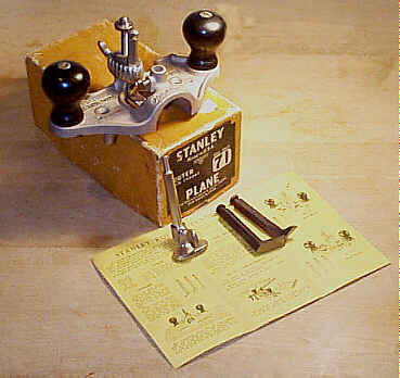
#71 Router plane, 7 1/2"L (7 5/8", 1962 on), various widths, 2 5/8lbs, 1885-1973.
 And here you thought
routers are the stuff of the modern workshop. Nope! They've
been around much
longer than the abNORMal kind has, but these kind ain't the
'lectrical kind.
These kind are pushed or pulled, and are suited for
smoothing the bottom of a
groove, mortice, or whatever, which is lower than the
general surface of the
piece being worked. They were very popular tools, especially
with patternmakers
and stairbuilders. Every shop should have one. Stanley's
minister of propaganda,
in a leaflet distributed with the tool, stated:
And here you thought
routers are the stuff of the modern workshop. Nope! They've
been around much
longer than the abNORMal kind has, but these kind ain't the
'lectrical kind.
These kind are pushed or pulled, and are suited for
smoothing the bottom of a
groove, mortice, or whatever, which is lower than the
general surface of the
piece being worked. They were very popular tools, especially
with patternmakers
and stairbuilders. Every shop should have one. Stanley's
minister of propaganda,
in a leaflet distributed with the tool, stated:
"For surfacing the bottom of grooves or other
depressions parallel
to the surface of the work. There are many applications in
pattern making
cabinet work and in fact almost all kinds of woodworking
that call for these
tools. They are particularly practical for routing dadoes
for shelves, stair
stringers or where pieces of hardware are to be recessed
into the surface or
edge of a board, such as large hinges or lock strikes,
etc. It is not possible to
show all these, but the user will soon discover places
where these tools will
prove their value."
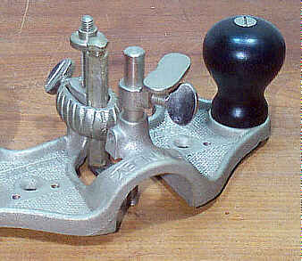
They are sorta D-shaped, with two turned hardwood
knobs (beech or maple) on
each end. The knobs flank an adjustable L-shaped cutter,
which protrudes
through a large, circular opening in the plane's sole. A
grooved post receives
the cutter, which is locked into position by a thumb screw
activated clamping
collar. This collar, as well as the cutters, are very easy
to lose, and these
planes are often found minus them. The grooved post is also
grooved on its
backside so that the cutter can be reversed, making the
plane function in a
bull nose fashion.
Originally, it came with only two cutters - 1/4"W and
1/2"W. These
two cutters are ground to a straight edge, so that they
operate just like a
paring chisel. They weren't well suited for smoothing, due
to tearout, so a
third, patented cutter was added in 1917. This one is
V-shaped.to make it
function like a plough (the farmer's kind) as it cuts the
wood. The earliest
version of this cutter is a one-piece construction, and can
sometimes be found
with the patent date stamped in its shank. Because the V
cutter has two bevels
on it, it proved difficult to grind and hone. Subsequently,
the cutter became a
two-piece design so that the end be removed for sharpening.
Late production
models of this plane have all three of their cutters
graduated in 1/16ths along
their shanks for fine adjusting.
The plane underwent many modifications during its
production by Stanley. The
first of which was arching the portion of the sole, forward
of the cutter, into
an open throat configuration. This was done ca. 1890. Then,
probably during the
mid-1890's, a mechanism to close the throat's opening was
added so that the
plane could work narrow surfaces, like grooving the edge of
a board, to add
lateral stability to the tool. This mechanism, or 'shoe' as
Stanley called it,
attaches to the round depth gauge rod that slips through the
arched area of the
main casting and 'closes' the throat to give more of a
bearing surface, or
sole, on the tool. It took Stanley a few designs to get this
right as the first
design of the shoe has a separate cutter collar casting that
projects forward
to carry the shoe and the depth gauge rod. Stanley soon
redesigned this to the
simpler method most are familir with today; the newer design
was less costly to
manufacture and much easier to use. The shoe's use is very
limited for most
work, but functions best as a depth stop, which is explained
next.
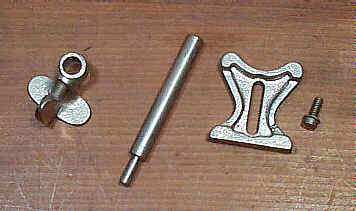
 At the same time the
shoe
was added, a round depth gauge rod was made part of the shoe
clamping assembly.
This rod controls the tool's depth of cut as the cutter is
adjusted deeper. It
permits consistency from cut to cut, which would be
difficult to achieve were
the rod not provided. The rod has a smaller diameter portion
on one end. The
use of the stop might not be intuitive to most, but it's
very easy to use and
rather clever in its simple operation. The rod is slipped
through the round
opening for it, atop the arched portion of the main casting,
so that the
smaller diameter is downward. The tshoe is then slipped onto
the rod (over the
large diameter) so that the shoe is above the arched portion
of the main
casting. The rod is then positioned to the desired depth
(relative to the sole
of the main casting) and the screw of the shoe is tightened
onto the rod. The
rod is left free to move up/down through the arched portion
of the main casting
- do not tighten the screw to lock it in place. As the cuts
are made, the rod
will slip down toward the casting until the shoe stops it
from moving downward
anymore. Once the shoe makes contact with the arched portion
of the main
casting, the desired depth has been reached. Pretty simple,
eh?
At the same time the
shoe
was added, a round depth gauge rod was made part of the shoe
clamping assembly.
This rod controls the tool's depth of cut as the cutter is
adjusted deeper. It
permits consistency from cut to cut, which would be
difficult to achieve were
the rod not provided. The rod has a smaller diameter portion
on one end. The
use of the stop might not be intuitive to most, but it's
very easy to use and
rather clever in its simple operation. The rod is slipped
through the round
opening for it, atop the arched portion of the main casting,
so that the
smaller diameter is downward. The tshoe is then slipped onto
the rod (over the
large diameter) so that the shoe is above the arched portion
of the main
casting. The rod is then positioned to the desired depth
(relative to the sole
of the main casting) and the screw of the shoe is tightened
onto the rod. The
rod is left free to move up/down through the arched portion
of the main casting
- do not tighten the screw to lock it in place. As the cuts
are made, the rod
will slip down toward the casting until the shoe stops it
from moving downward
anymore. Once the shoe makes contact with the arched portion
of the main
casting, the desired depth has been reached. Pretty simple,
eh?
Next, in 1902, a vernier cutter adjustment mechanism
was added to the
grooved post; the cutters were redesigned to have a notch at
their top to
engage a wheel, which traverses a threaded rod to regulate
the cutter's depth.
This vernier adjustment made it possible to make fine
advances in the cutter's
set than is normally made when done manually. The feature
makes it possible to
advance the cutter in successive fine increments as the
recess is cut deeper
and deeper; i.e., instead of hacking out the recess with
just a few settings of
the iron, you rout the area with the cutter in a fine set,
loosen the blade
clamping collar, turn the vernier wheel a bit, clamp the
cutter firmly, then
rout the area. This procedure is repeated over and over
until the desired depth
is reached.
In 1909, countersunk (from above) screw holes,
through the sole, were added
to allow wood bottoms or fences to be attached. This allows
the tools to work
recesses that are larger than the tool is wide. In other
words, the tool can be
made physically 'larger' by attaching a wooden sole to it.
In the same year, 1909, the shoe to close the throat
was redesigned and
repositioned so that it became part of the arched portion of
the main casting.
During this redesign, the depth gauge rod was repositioned,
and in fact, the
shoe attaches directly to the rod.
 An adjustable fence,
which is screwed to the sole, was added in 1939. It is
fastened to the
underside of the tool's sole by means of a single screw and
washer, both of
which are often missing. Two small screw holes that flank a
larger screw hole
(on either side of the cutter) indicate whether your version
originally came
equipped with the fence. The sole is also grooved to receive
the fence. The
fence is used for the times when the cutter is run parallel
to an edge. The
fence has a straight edge for straight work, and the other
side is curved to
allow the tool to follow either concave or convex edges.
An adjustable fence,
which is screwed to the sole, was added in 1939. It is
fastened to the
underside of the tool's sole by means of a single screw and
washer, both of
which are often missing. Two small screw holes that flank a
larger screw hole
(on either side of the cutter) indicate whether your version
originally came
equipped with the fence. The sole is also grooved to receive
the fence. The
fence is used for the times when the cutter is run parallel
to an edge. The
fence has a straight edge for straight work, and the other
side is curved to
allow the tool to follow either concave or convex edges.
As is the case with many Stanley planes, the first
models were japanned. The
earlier models have maple handles that are finished with a
clear varnish.
Toward the close of the last century, they became nickel
plated. This plane
follows that same course. The later models have hardwood
knobs that are painted
black, while even later models have composition or plastic
knobs. The plane is
still being made in England, but its quality pales in
comparison to the older
American versions.
You'll also see many of these planes cast in brass.
Stanley never made them
in this metal. The source of these brass planes is from the
many patternmakers
who made copies of ones they borrowed. It is an easy plane
to make, and with it
being particularly useful in the patternmaking trade, it was
inevitable that
enterprising patternmakers would 'roll their own' and save
themselves some
dinero.
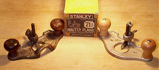
#71 1/2 Router plane, 7 1/2"L, various widths, 2 1/8lbs, 1896-1949.
 Good old Stanley, coming
up with a new model number to designate a plane that was
born after the
redesign of the #71.
This plane is nothing but the first model version of the #71! It has a closed
throat; i.e., there is no arching of the sole forward of
the cutter. It did
follow the same evolution of features, except for the
throat adjusting
mechanism, as found on the #71. It was a less expensive
version of the #71.
Good old Stanley, coming
up with a new model number to designate a plane that was
born after the
redesign of the #71.
This plane is nothing but the first model version of the #71! It has a closed
throat; i.e., there is no arching of the sole forward of
the cutter. It did
follow the same evolution of features, except for the
throat adjusting
mechanism, as found on the #71. It was a less expensive
version of the #71.
One might wonder why Stanley chose to manufacture the
two different models
of the routers, which only differ in the portion of the sole
ahead of the
cutter. Stanley claimed that the open throat of the #71 allows for easier passage of
the shaving, and that
it's easier for the worker to view the cutter's edge as
the tool is being
worked. However, there are some applications where the
open throat design
proved difficult to use, such as grooving a narrow piece
of work, in which case
the more sole that makes contact with the wood, the easier
it is to control the
tool's lateral stability. The #71 was hyped to be more versatile
and user friendly,
but at a greater cost than the simpler #71 1/2, which can do all that the #71 can. The image of
the two routers shows the differences in the throats; the
one on the left is an
earlier model of the #71 and has the open throat, while
the one on the right
is a #71 1/2 with its closed
throat.
There are fewer #71 1/2's out there
than there are of its non fractional sibling which should
clue the reader that
many guys didn't go for the closed throat design back
then. Even today, they
are tougher to sell to users, who prefer all the bells and
whistles that the #71 offers.
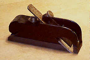
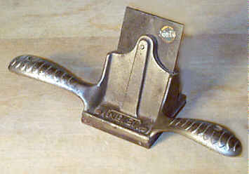
#72 Chamfer plane, 9"L, 1 5/8"W, 3 3/8lbs, 1886-1938. *
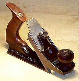 This plane is used to
chamfer the edges of stock, although it can't do stopped
chamfers all that
well. The plane has an inverted V-shaped sole, with each
"leg" of the
V serving as a guide while the plane is worked. Located
toward the front of the
plane is an inclined area onto which an adjustable sole
section is secured; the
mating surface between the main casting and the adjustable
sole is a broad
tongue and groove joint, with the adjustable sole part
carrying the tongue.
This plane is used to
chamfer the edges of stock, although it can't do stopped
chamfers all that
well. The plane has an inverted V-shaped sole, with each
"leg" of the
V serving as a guide while the plane is worked. Located
toward the front of the
plane is an inclined area onto which an adjustable sole
section is secured; the
mating surface between the main casting and the adjustable
sole is a broad
tongue and groove joint, with the adjustable sole part
carrying the tongue.
The adjustable portion of the sole carries the
cutter, and can be raised or
lowered to decrease or increase, respectively, the width of
the chamfer. With
the sole positioned in its lowermost position, the plane can
function as a
smoother. A brass five-spoked adjusting wheel (later
examples have a nickel
plated adjusting wheel) is used to secure the sole in the
desired position. It
can strip out from repeated hard use, so it's worth checking
that. A small
washer, usually long lost, fits below the spoked adjusting
wheel.
 A typical rosewood
tote
and knob, like those found on the bench planes (the #3's are the exact size), are
used to push the plane.
The cutter is single (it has no cap iron). The plane's
original cutter is
sometimes lost, and replaced with one from a common block
plane. Remove the
lever cap and inspect the backside of the blade; an
original cutter will not
have a series of grooves, like those of a block plane,
machined into it. A
bullnose sole, which is usually long-lost, was added in
1909 to help the plane
cut stopped chamfers (you still have to work the stopped
areas by hand,
however, since there is an amount of sole ahead of the
iron). The image below
shows the plane with the bull nose section.
A typical rosewood
tote
and knob, like those found on the bench planes (the #3's are the exact size), are
used to push the plane.
The cutter is single (it has no cap iron). The plane's
original cutter is
sometimes lost, and replaced with one from a common block
plane. Remove the
lever cap and inspect the backside of the blade; an
original cutter will not
have a series of grooves, like those of a block plane,
machined into it. A
bullnose sole, which is usually long-lost, was added in
1909 to help the plane
cut stopped chamfers (you still have to work the stopped
areas by hand,
however, since there is an amount of sole ahead of the
iron). The image below
shows the plane with the bull nose section.
 The planes do not use
a
cammed lever cap like those on the common bench planes.
Instead, the lever cap
is a japanned cast iron piece that is activated by thumb
screw. The earlier
models, such as that in the image, use the same japanned
thumb screw that's
common to specialty planes of the same vintage such as the #78. Later examples have the
nickel plated lever thumb
screws that have "STANLEY" embossed in them. The latest
models have
the nickel plated flat thumb screws with the fine knurling
about the
circumference.
The planes do not use
a
cammed lever cap like those on the common bench planes.
Instead, the lever cap
is a japanned cast iron piece that is activated by thumb
screw. The earlier
models, such as that in the image, use the same japanned
thumb screw that's
common to specialty planes of the same vintage such as the #78. Later examples have the
nickel plated lever thumb
screws that have "STANLEY" embossed in them. The latest
models have
the nickel plated flat thumb screws with the fine knurling
about the
circumference.
The earlier models will have a beaded knob and the
patent date cast into the
right side of the plane. The iron, which is bedded bevel
side down, can also be
found with the patent date, "PAT APR. 21, 85", stamped in
the iron
right below the Stanley name.
Curiously, many of the planes can be found with holes
drilled into the main
casting from both sides. Guys would fit a piece of wood or
metal into the V
portion of the sole so that the plane has a sole like a
common smoothing plane;
i.e., the wood or metal acts as a filler, with the holes in
the main casting to
permit screws to hold the filler in place. It might seem odd
that this filler
would be inserted into the sole, but it was done so that the
plane would cut
along the edge of stock. Were the plane not retrofitted with
this filler, only
the plane's toe would be the flat bearing surface of the
tool, which is far too
little an area when planing an edge, an edge normally
narrower than the width
of the plane's iron; i.e. were the filler not in place, the
heel would want to
bear on the edge, with the toe being raised off the edge.
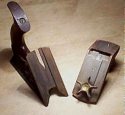
#72 1/2 Chamfer plane, 9"L, various widths, 4 1/8lbs (total), 1887-1918. *
 This plane is identical
to the #72, except
that it has an additional attachment for molding the
chamfers. The attachment
could be bought separately, but it seems that not too many
guys bought them as
they aren't that numerous. They are a real pain in the
arse to use, even though
they are supposed to function just like the #69 does.
This plane is identical
to the #72, except
that it has an additional attachment for molding the
chamfers. The attachment
could be bought separately, but it seems that not too many
guys bought them as
they aren't that numerous. They are a real pain in the
arse to use, even though
they are supposed to function just like the #69 does.
This attachment is secured to the plane like the
other soles are with the
spoked wheel that tightens it to the plane's main casting.
The attachment has a
two-piece cast iron construction, where the lower piece (the
one that carries
the cutter) slips under the upper piece (the one that
carries the spoked
wheel). The two pieces are held together with a screw that
has a knurled adjusting
'nut' midway along the screw. This screw allows the lower
section to be raised
or lowered relative to the upper piece so that the depth of
cut can be
regulated.
The cutters supplied with the attachment are
identical to those supplied
with the #69.
The cutters scrape a bead, reed, or flute on a flat
chamfer after that is cut
by the plane using one of the normal soles. The plane
itself is marked #72 but the beading
attachment has no markings, save for the patent dates that
are normally found
stamped into the blade securing nut. This nut, originally
brass and slotted,
was later made as a nickel plated thumb screw. The cutter
is held in place with
a staple like cast clamping piece. If this clamping piece
is broken or missing,
good luck trying to make it look original.
The plane is very seldom found with all its parts
(bull nose, regular sole,
and beading attachment). If you're a collector, buying just
the molding attachment
alone, with its cutters, can set you back a few bucks. The
earliest models have
polished brass on all but the two cast iron pieces, but the
later ones are
finished with nickel plating.
Check that the adjusting wheel isn't stripped. Also
check the lower piece
where the adjusting screw engages as it buttresses the
cutter's carrier. This
area is rather small and somewhat fragile and can crack.
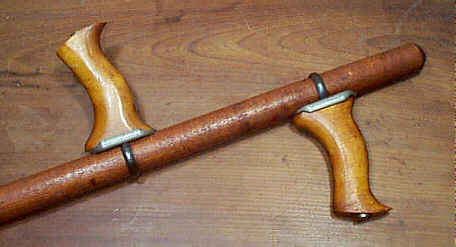
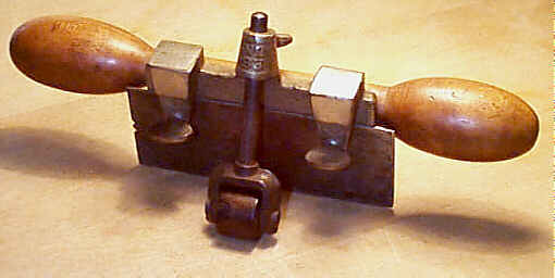
#74 Floor plane, 10 1/2"L, 2 5/8"W, 10lbs, (21 1/2lbs 1909 on), 1886-1923. *
 Don't think many of us
are gonna be using this one. It was designed to plane broad
wooden surfaces
such as bowling alleys, ship decks, floors, or whatever.
This is Stanley's only
plane that is used not on a bench in the standing position -
a long handle is
used to push the plane. It's also one of the most difficult
planes to find in
original condition; for example, it's far easier to find a #196 or #212 than it
is to find one of these in minty unmodified condition with
the original handle.
Don't think many of us
are gonna be using this one. It was designed to plane broad
wooden surfaces
such as bowling alleys, ship decks, floors, or whatever.
This is Stanley's only
plane that is used not on a bench in the standing position -
a long handle is
used to push the plane. It's also one of the most difficult
planes to find in
original condition; for example, it's far easier to find a #196 or #212 than it
is to find one of these in minty unmodified condition with
the original handle.
The plane has a 45" long turned (round) handle that
slips into a
pivotting hollowed receiver that's attached on the main
casting, below the
blade. The handle is maple or beech (I've seen a birch one,
too) and is tapered
from its overall diameter of 1 1/8" down where it joins the
receiver.
On the handle are two maple or beech totes. Each of
these totes sit atop a
nickeled casting to provide a flat base. The casting has a
hole through so that
a forging can pass through it; the lower end of the forging
is looped to slip
over the handle and the upper end is threaded to receive the
brass tote nut.
The brass tote nut is unique to this plane as it's oversized
from those used on
the common bench planes - it measures 5/8" diameter and is
13/16"
long.
The totes themselves are rather primitive looking
things (floor planing is a
rather oafish job afterall and there's really no need to
provide a Mercedes
when a Yugo will do) with a mostly 'vertical' profile. They
don't have
pronounced horns like those used on the bench planes. Some
users removed the
horns altogether so that they could butt the totes in the
palms of their hands
rather than wrap their hands around them.
 The totes can be
positioned anywhere along the length of the handle and
anywhere around the
handle. The brass tote nut is loosened with a screwdriver,
which then allows
the handle to be rotated or moved along the handle. When
tightened, the brass
nut draws the looped end of the forging upward against the
wooden handle to secure
it in the desired position. Many of the brass nuts are
munged from use. Many of
the totes are also damaged, more often than not cracked,
from use. Some guys
shim the tote nut with washers in the tote's countersunk
cavity so that the
tote nut stands proud of the top of the tote.
The totes can be
positioned anywhere along the length of the handle and
anywhere around the
handle. The brass tote nut is loosened with a screwdriver,
which then allows
the handle to be rotated or moved along the handle. When
tightened, the brass
nut draws the looped end of the forging upward against the
wooden handle to secure
it in the desired position. Many of the brass nuts are
munged from use. Many of
the totes are also damaged, more often than not cracked,
from use. Some guys
shim the tote nut with washers in the tote's countersunk
cavity so that the
tote nut stands proud of the top of the tote.
Most of the planes are found without the handle. It's
a good bet that guys
found them better for staking tomatos than for floor
planing. Most of the
handles found on the planes are latter day reproductions. A
missing handle seriously
devalues the collectibility (and that's all the plane is
good for, right?) of
it - an original handle is worth more than the plane itself.
The main casting is just the #101 on tool sterrhoids, but with
the aforementioned
pivotting receiver. The receiver is secuted to the main
casting with a rod that
screw through the cheeks of the plane (the rod is slotted
on the left side).
Check that the receiver isn't damaged where it pivots
about the rod - it can
crack or break out there.
A double iron is used in this tool. The iron is the
same as that used on the
#8 sized
bench planes, but the cap iron is unique to the plane as
it isn't cut out to
accept an adjusting fork; the iron is adjusted manually.
If you need a cap
iron, good luck finding it as this is the only Stanley
plane that was equipped
with such a cap iron. In fact, the only part you can snarf
from this plane to
use on others is the iron. But, you'd be foolish to do
that, so don't.
The iron rests upon two sloping projections that
arise from the main
casting. These projections are milled so that they are
coplanar. The iron is
held in place with a simple lever cap; the lever cap is
oversized and has a
notch cast on its front so that it can slip under and engage
another rod
(screwed through the cheeks) when the lever cap screw is
turned. The lever cap
screw is nickel plated and has "STANLEY RULE & LEVEL
CO."
embossed around it much like that found on the #113. The earlier models of the
plane have the patent
date, "PAT. DEC.15-85.", embossed at the rear of the main
casting.
The plane is sometimes found modified. As mentioned
earlier, the totes are
reshaped. The plane can also be found with the sides of the
sole chamfered to
reduce the surface area in an attempt to cut down friction.
Sometimes wooden
soles are screwed to the main casting. The most common
modification is the
handle receive is drilled to accept a screw so that the
handle can be secured
to the plane. It seems Stanley forgot this important
feature. Some guys also
bend the heel of the iron upward to allow for a greater
range of movement on
the handle receiver.
Being 6' 3" tall, I can't find a position of the
totes to make for a
comfortable grip. One would likely be bent over somewhat to
use this thing and
I suspect workmen's compensation would go bankrupt if there
ever were a wave of
floor planing with this thing. Have pity on those old
hunchbacks you see
lurking around your local Acme Bowling Lanes for they
probably suffered these
planes during their youth. Lucky for us floor sandahs was
invented, hunh?
#75 Bull nose rabbet plane, 4"L (4 1/8", 1936 on), 1"W (1 1/16", 1936 on), 5/8lbs, 1879-1973.
 This is a cheap, little
rabbet plane, that is very useful in the shop. It has a top
section that arches
forward of the blade to form the front portion of the sole.
This section is
adjustable, forward and backward, to regulate its mouth.
This is done by means
of a simple screw, which is threaded to lower section, the
rear portion of the
sole, of the plane. A washer sits under the screw, with the
earlier examples
having a brass washer. The plane does not have its number
cast into it. The
lower portion of the plane's sides is machined, with the
rest above the
machined area japanned.
This is a cheap, little
rabbet plane, that is very useful in the shop. It has a top
section that arches
forward of the blade to form the front portion of the sole.
This section is
adjustable, forward and backward, to regulate its mouth.
This is done by means
of a simple screw, which is threaded to lower section, the
rear portion of the
sole, of the plane. A washer sits under the screw, with the
earlier examples
having a brass washer. The plane does not have its number
cast into it. The
lower portion of the plane's sides is machined, with the
rest above the
machined area japanned.
The lever cap has a thumb screw to hold it and the
iron in place (earlier
examples will have a slotted screw). There are two lugs cast
into the top
section under which the lever cap fits. Sometimes the lever
cap is snapped and
repaired. The plane can choke easily since the lever cap
serves as the chip
breaker and it sits well back from the cutting edge. Despite
the tendency to
choke, the plane is useful for trimming and odd rabbeting. I
found it very
useful when cleaning up years of grunge and paint within the
window frames of
double hung sash.
The section of the sole ahead of the iron is not
co-planar with the sole
behind the iron. The plane is purposely made this way to
assist it with its cut
(you guys what owns the 'lectrical jointahs should know why
the plane's sole is
the way it is) so there's no need to practice sole lapping
on it.
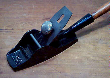
#78 Duplex filletster and rabbet plane, 8 1/2"L (8 1/4", 1936 on), 1 1/2"W, 3lbs, 1885-1973.
 This is another popular
Stanley plane, on which the company built a great fortune.
Nearly every workman
of the time had one of these planes in their kits. This
plane was so popular
and functional, that it still is made today. Any handtool
enthusiast should consider
this plane, or one like it, be it a competitor's or a wooden
version, as part
of his arsenal.
This is another popular
Stanley plane, on which the company built a great fortune.
Nearly every workman
of the time had one of these planes in their kits. This
plane was so popular
and functional, that it still is made today. Any handtool
enthusiast should consider
this plane, or one like it, be it a competitor's or a wooden
version, as part
of his arsenal.
The plane has two beds for the cutter - one
positioned for normal work, and
the other for bullnose work. The cutter has no cap iron, and
is held in place
by a thumb screw activated lever cap. Earlier models, with
the common floral
vines cast into the handle, required hand adjustment to set
the iron, but in
1925, a lever, which engages machined grooves in the
backside of the iron, was
provided to accomplish this. Around 1910, the handle has a
fish scale-like
pattern cast into it.
There is an adjustable depth stop on the right hand
side of the plane,
secured in place by a thumb screw. Directly below the depth
stop, is a
three-pronged spur to score the grain that sits flush with
the side of the
plane. It can be turned up out of the way when it isn't
needed. There is no
spur on the left of the plane.
A rod, threaded on one end, is used as the arm on
which the fence is
secured. The arm can be attached either to the left of the
plane, for working
right-handed, or to the right of the plane, for reversing
the plane to work
left-handed. This is a nice feature designed to handle
problem grain while
working. However, there is no provision for the depth stop
on the left side of
the plane, so you'll need to plane to a gauged line, or do
it by eye, when
using the plane left-handed. The threaded rod has a hole
drilled through it on
its end. This hole permits a nail, or something similar, to
pass through it in
order to tighten or loosen the rod. Many of the rods are
bent right where the
threads start so check this area by unscrewing the rod -
you'll notice whether
it's bent as you unscrew it.
The fence is secured to the arm with a thumb screw.
Sometimes you'll find
examples where the thumb screw is replaced with a slotted
round head screw.
This is due either to the thumb screw being misplaced, or
the original thumb
screw being stripped. Also, the fence is sometimes broken;
when the fence is
attached to the left side of the plane, the back portion of
the fence is longer
than the front portion by about 3/4". Look at the fence,
with the thumb
screw toward you. The aperture for the arm should noticeably
be to the left.
This plane is often found with parts missing - most
often it is the depth
stop and/or fence. You can usually scrounge parts from other
models, but this
approach usually ends up costing you more for an assembled
one than it does for
buying a complete one. It's also possible to find the plane
with the section of
the sole ahead of the bull nose bed snapped off. Some guys
ground this section
off so that they could use the plane as a chisel plane or to
worked stopped
rabbets right to their very end, which can't be done with
this portion of the
sole present. Planes that were accidently broken will have
the section brazed
back onto the main casting.
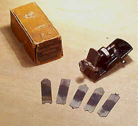
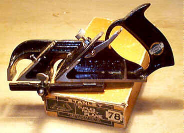 The #78 pictured with its original box
dates from the
1920's, with the most obvious clue being the depth
adjustment lever for the
cutter. It has the common decal on the handle, which
Stanley applied to many of
their planes and other handtools. It can be found applied
to the totes on the
Bailey and Bed Rock bench planes, special purpose planes
such as this one,
sliding bevels, try squares, etc. The block planes and
some of the other
smaller planes, like the #95, used a smaller decal that's
noticeably yellow (see
the #220 for an example of this decal).
The #78 pictured with its original box
dates from the
1920's, with the most obvious clue being the depth
adjustment lever for the
cutter. It has the common decal on the handle, which
Stanley applied to many of
their planes and other handtools. It can be found applied
to the totes on the
Bailey and Bed Rock bench planes, special purpose planes
such as this one,
sliding bevels, try squares, etc. The block planes and
some of the other
smaller planes, like the #95, used a smaller decal that's
noticeably yellow (see
the #220 for an example of this decal).
This #78 also illustrates another
common occurrence with Stanley - the use of early labels
on boxes of later
planes. The label on this plane, often called the "picture
label"
because of the line drawing of the tool contained within,
was in widespread use
starting around 1905. When this plane was made, Stanley
was in the midst of
what is known as the sweetheart era, where tools have the
heart logo stamped in
them somewhere. Even the box labels had a tiny heart on
them as part of the
logo. However, Stanley was also frugal in their
unwillingness to toss something
that was still perfectly usable, in this case a label. So,
here is a plane made
during the 1920's with a label used a few decades earlier.
Keep in mind that
it's impossible to date accurately Stanley stuff by the
boxes alone. Generally,
the latest feature on the tool, in this case the label, is
the more accurate
clue to the plane's approximate date of manufacture.
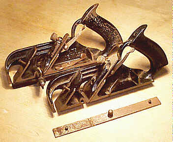
#78W Weatherstrip (Door) rabbet plane, 8 1/4"L, 1 1/2"W, 3lbs, 1936-1943. *
 This is a very special
purpose plane, which none of us are likely to use. It is
designed for the
installation of weather stripping. The plane is like the
normal #78, except there is a
detachable steel runner on the sole of the plane. This
acts as a gauge for
cutting a 3/8" rabbet on either side of the plane, without
the need to
adjust the plane to do so. Stanley claimed that this
rabbet cut was
particularly useful for installing the weatherstripping on
the lock jamb and
the head of the door. Since the gauge is centered, the
plane can be worked left
or right handed (in other words, reversed) so that it
won't split out the grain
on the end of the door.
This is a very special
purpose plane, which none of us are likely to use. It is
designed for the
installation of weather stripping. The plane is like the
normal #78, except there is a
detachable steel runner on the sole of the plane. This
acts as a gauge for
cutting a 3/8" rabbet on either side of the plane, without
the need to
adjust the plane to do so. Stanley claimed that this
rabbet cut was
particularly useful for installing the weatherstripping on
the lock jamb and
the head of the door. Since the gauge is centered, the
plane can be worked left
or right handed (in other words, reversed) so that it
won't split out the grain
on the end of the door.
The plane does not have the number 78W cast into it,
and looks like any
regular #78,
especially since the runner is often missing on the plane.
The dead give-away
of this plane is a captive knurled locking nut or
pivotting steel locking lever
located right below the cutter adjustment. The nut or
lever locks the runner to
the sole of the plane.
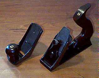
The runner has two pins - one located toward the
front and the other toward
the back - which fit into holes that are drilled through the
plane's sole. At
about the mid-point of the runner is attached a projecting
boss, onto which the
the locking means is fixed above. There are several means by
which the runner
is locked in place. Some models carry a captive nut on the
main casting, and
engage threads on the boss. Others, like the two illustrated
here, have
pivoting levers that engage a groove machined on the boss.
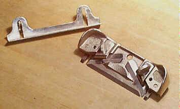
Stanley did not originate this idea. Some unknown
firm retro-fitted #78's a decade or two
earlier, and then resold them. These models have a runner
with two long
pin-like projections that engage the plane. The runner
locking mechanism is a
bit different in that it is a pivoting piece of metal that
swings into place to
engage a hook-like projection on the runner. There is an
elongated slot milled
into the sole of the plane to accomodate the hook-like
piece of the runner.
#A78 Duplex filletster and rabbet plane, 8 1/4"L, 1 1/2"W, 1 1/4lbs, 1925-1934. *
Thankfully, the last of the aluminum abberations. Same as the #78, but cast in aluminum, including the fence, lever cap, and depth stop. If you're a collector, don't buy one that has iron anything on it.
Just imagine if this thing sold like no tomorrow
giving Stanley fits of
aluminum marketing opportunities. I'd probably be writing
about an aluminum
shootboard or something like that.
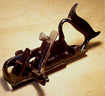
#79 Side rabbet plane, 5 1/2"L, 1/2"W, 5/8lbs, 1926-1973.
 The #79 is a popular plane (heck, it's
one the few that is
still available new). The only knock against it that I
have is that the
trailing cutter's set ought to be backed off completely so
that it doesn't drag
behind the leading cutter, which is what is doing the
actual cutting. The #79 is also longer than the #98/#99 pair,
which may be a concern if you're working small areas. The
depth stop has two
screws that must be loosened/tightened when adjusting it.
Those are the only
real differences.
The #79 is a popular plane (heck, it's
one the few that is
still available new). The only knock against it that I
have is that the
trailing cutter's set ought to be backed off completely so
that it doesn't drag
behind the leading cutter, which is what is doing the
actual cutting. The #79 is also longer than the #98/#99 pair,
which may be a concern if you're working small areas. The
depth stop has two
screws that must be loosened/tightened when adjusting it.
Those are the only
real differences.
These are handy little goobers used to clean up
rabbets, dados, and grooves.
There are two opposing cutters locked in place with thumb
screws. The plane can
be used for left or right cuts. There are two nose pieces
which are reversible
to allow for bullnose work (the first image shows the plane
in its bull nose
configuration).
If anything bad can be said about this plane's use,
it has to be that its
cutters are too narrow. There are times when a rabbet is
larger than this plane
can handle. For these rabbets, the wooden plane versions of
the side rabbets
are ideally suited - they are capable of cleaning up rabbets
up to ~2"
wide or deep.
 The earlier models
have a
semi-circular cutout on the top of the plane, between the
two cutters. Later
planes, starting ca. 1950, don't have this cutout, but do
have a hole in the
middle for hanging the plane on a hook. A depth stop, which
runs nearly the
full length of the plane, was also added about the same
time. The depth stop is
held in place by two small nickel plated thumb screws, but
the last production
American ones use slotted screws as do the current English
manufactured models.
The depth stop is made of stamped steel. You can find first
model examples that
are modified to accept a homemade depth stop.
The earlier models
have a
semi-circular cutout on the top of the plane, between the
two cutters. Later
planes, starting ca. 1950, don't have this cutout, but do
have a hole in the
middle for hanging the plane on a hook. A depth stop, which
runs nearly the
full length of the plane, was also added about the same
time. The depth stop is
held in place by two small nickel plated thumb screws, but
the last production
American ones use slotted screws as do the current English
manufactured models.
The depth stop is made of stamped steel. You can find first
model examples that
are modified to accept a homemade depth stop.
The cutters are secured with small cast iron clips,
which are held to the
main casting with small thumb screws. These thumb screws, as
well as the thumb
screws that are used to hold the depth stop, can strip out.
Be sure to check
these as it's a fairly common problem on this plane and the
#98 and #99. The
screws that hold the nose piece in place are countersunk
so that they don't
interfere with the plane's cutting action. These screws
are often seized in
place from the plane's sitting idle for so long.
Some common damage to be aware of for this plane, and
the #98 and #99 side
rabbets, is a stress crack that runs parallel to the
cutter. The crack is easy
to spot by examining the plane from its backside, the flat
side of the plane.
Look carefully about the top of the mouth to the side
where the bed meets the
mouth. The crack is usually the result of too much
pressure being applied by
the plane's blade clamping device, which is nothing but a
cast piece secured by
a thumb screw. On the models with the depth stop, you have
to remove it to
examine the areas for stress cracks.
Most of these planes are found fully nickel plated.
During WWII, the plane
was japanned. These models are fairly scarce.
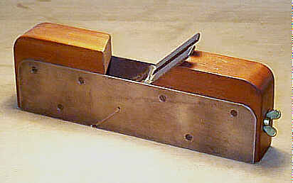
#80 Steel cased rabbet plane, 9"L, 1 1/2"W, 1 5/8lbs, 1877-1888.
 These are hybrid planes,
where wooden plane meets metal plane in a short-lived union.
In fact, these are
Stanley's only planes they ever offered that may remotely be
considered wooden
planes. Stanley may have made these planes as their answer
to the finer infill
planes that were all the rage in England. Of course, this is
pure speculation,
but it does seem strange that an iron plane slinging company
would take to
making a plane that sure has a goodly amount of wood as part
of it.
These are hybrid planes,
where wooden plane meets metal plane in a short-lived union.
In fact, these are
Stanley's only planes they ever offered that may remotely be
considered wooden
planes. Stanley may have made these planes as their answer
to the finer infill
planes that were all the rage in England. Of course, this is
pure speculation,
but it does seem strange that an iron plane slinging company
would take to
making a plane that sure has a goodly amount of wood as part
of it.
The plane is made up of a one piece U-shaped metal
sole, which is bent
upward to form the sides of the plane. Sandwiched inside
this chunk of metal
are two pieces of wood stuffing - one forward of the cutter,
and one behind the
cutter (as the bed). These pieces of wood are secured to the
metal with
countersunk screws. The wood stuffing has the patent date
stamped forward of
the cutter, and the company logo behind the cutter. The
plane is not marked
with the model number.
A long rod extends through the back piece of wood,
onto which a cast iron
japanned clamp is attached on the cutter side, with a brass
thumb screw (over a
brass washer) threaded on the heel. When the thumb screw is
turned, it pulls
the clamp up against the slotted cutter, increasing the
pressure on it to hold
the cutter in place. This method of securing the cutter is
nearly identical to
one of the first blade securing mechanisms ever patented in
this country - the
one by Thomas Worall, a former Baptist minster turned
planemaker. His patent of
1856, while working in Charlestown, Boston, and Lowell, MA,
had to be the
inspiration for the later Stanley design, and Stanley didn't
have to worry
about patent infringement as the Worall patent had expired
by the time Stanley
put this plane in production.
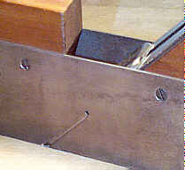 These planes are very
difficult to find in good condition. Makes a guy wonder
whether the planes were
used for rabbeting railroad ties, or something like that.
Most of the planes
have their mouths filed wider to open them up, probably
because many an
American woodworker of the day wouldn't appreciate a tight
mouth if it came up
and hit him on his, well, his mouth. Actually, the planes
have a major design
problem - they choke very easily with the mouth as Stanley
provided, and in
order for them to work well, the mouth had to be filed open
somewhat; the face
of the iron, along its edges, butts right against the steel
(see the #90 version of
this plane for an image of the other side of the plane,
where there is a very
slight relief to the steel ahead of the iron, but only for
a too short
distance). Thus, you're more likely to find the proverbial
needle in a haystack
before you find one of these planes that hasn't been on
the wrong end of a
file.
These planes are very
difficult to find in good condition. Makes a guy wonder
whether the planes were
used for rabbeting railroad ties, or something like that.
Most of the planes
have their mouths filed wider to open them up, probably
because many an
American woodworker of the day wouldn't appreciate a tight
mouth if it came up
and hit him on his, well, his mouth. Actually, the planes
have a major design
problem - they choke very easily with the mouth as Stanley
provided, and in
order for them to work well, the mouth had to be filed open
somewhat; the face
of the iron, along its edges, butts right against the steel
(see the #90 version of
this plane for an image of the other side of the plane,
where there is a very
slight relief to the steel ahead of the iron, but only for
a too short
distance). Thus, you're more likely to find the proverbial
needle in a haystack
before you find one of these planes that hasn't been on
the wrong end of a
file.
The plane was first offered without the iron skewed,
which is fine for
rabbeting with the grain, but Stanley soon realized that
most most wooden
rabbet planes have skewed irons to assist the plane when
working across the
grain, so they soon redesigned the plane to have a skewed
iron. The first model
also uses a captive lever cap and a round brass thumb screw
to secure the iron.
The lever cap pivots on a pin that is fastened to the steel
sides.
The clever reader might take notice that there are
two #80's offered
by Stanley. This plane, the wooden #90, and the
bull nose #11, are the only common Stanley
plane numbers that
were re-issued; there are two #80's
- this rabbet plane and the cabinet scraper (follows) -
and two #90's
- the other wooden rabbet plane - and two #11's - the beltmakers plane and
the bull nose
cabinetmaker's rabbet plane. The #80 and #90 planes were
never offered concurrently, so there was never any
confusion over which plane
was which, but the #11's were
offered concurrently, with the bull nose rabbet likely
only offered over in
England.
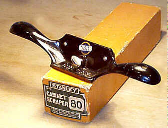
#80 Cabinet scraper, 11"L (11 1/2", 1947 on), 2 3/4"W, 1 3/4lbs, 1898-1984.
 The common scraper that
many a cabinetmaker owned, if he didn't want to burn his
fingers. The middle
portion of the cast iron tool is semi-rectangular in shape
and has two handles,
sorta gullwing-like, which flank the 'rectangle'. The blade
is fit into a
milled 'bed' of the rectangular area and is secured in place
with a flat bar of
metal; the blade tilts toward the flat bar. The flat bar
puts pressure against
the blade by means of two thumb screws that thread into the
main casting; this
arrangement is what secures the blade to the tool, and a
nail pushed through
the holes in the thumb screws permits the blade to be
secured tightly. To the
rear of the blade, on the other side of the casting, is
another thumb screw,
which when turned puts some pressure on the blade from
behind causing the blade
to bow or spring. This action puts a slight curve on the
blade and is, in
essence, the blade's depth adjuster; turning the thumb screw
to the right
increases the blade's set, while turning it to the left
decreases it. The
handles each have a hole drilled in them so that it can be
hung out of the way.
The common scraper that
many a cabinetmaker owned, if he didn't want to burn his
fingers. The middle
portion of the cast iron tool is semi-rectangular in shape
and has two handles,
sorta gullwing-like, which flank the 'rectangle'. The blade
is fit into a
milled 'bed' of the rectangular area and is secured in place
with a flat bar of
metal; the blade tilts toward the flat bar. The flat bar
puts pressure against
the blade by means of two thumb screws that thread into the
main casting; this
arrangement is what secures the blade to the tool, and a
nail pushed through
the holes in the thumb screws permits the blade to be
secured tightly. To the
rear of the blade, on the other side of the casting, is
another thumb screw,
which when turned puts some pressure on the blade from
behind causing the blade
to bow or spring. This action puts a slight curve on the
blade and is, in
essence, the blade's depth adjuster; turning the thumb screw
to the right
increases the blade's set, while turning it to the left
decreases it. The
handles each have a hole drilled in them so that it can be
hung out of the way.
The blade is ground to a 45 degree bevel and has the
hook turned toward the
flat side of the blade. When the blade is inserted into the
tool (do this from
the sole so that you don't injure the burr), be sure that
the hook is oriented
so that it's toward the direction in which the blade leans.
The tool is pushed
with the blade leaning away from you. A solid grip and
moderate downward
pressure on the handles will have you scraping in no time.
Your fingers will
thank you daily when you use this common tool. The one knock
on the tool is
that it doesn't have the fine adjusting mechanism that the #12 family of
scrapers do and that the blade can't be pitched for
optimal performance on a
given wood like the #12 can.
The entire plane is japanned, but the thumb screws
and flat bar are nickel
plated. The tool's vintage can be determined by the logo
stamped on the flat
bar and on the cutter. The first model of the scraper has
the leading edge
(relative to the direction the tool is pushed) of the main
casting cast
straight across, whereas the later models have the same edge
cast convex. The
earliest model has the patent date embossed into the tool.
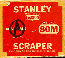
#80M Cabinet scraper, 11"L, 2 3/4"W, 1 3/4lbs, 1930-1974.
 This is the malleable
iron version of the tool, probably aimed at the punks that
populated the trade
schools to keep the tool intact after they got done throwing
it at each other,
running it through the tablesaw, using it as a doorstop,
etc. The plane is
embossed "80M". This model isn't found as frequently as its
grey iron
brother, the #80,
but that doesn't make it valuable, except as a user or
maybe even as a
boomerang in the outback.
This is the malleable
iron version of the tool, probably aimed at the punks that
populated the trade
schools to keep the tool intact after they got done throwing
it at each other,
running it through the tablesaw, using it as a doorstop,
etc. The plane is
embossed "80M". This model isn't found as frequently as its
grey iron
brother, the #80,
but that doesn't make it valuable, except as a user or
maybe even as a
boomerang in the outback.
Curiously, Stanley chose to slap a red label on the
box for this tool
instead of the common green label that was in widespread use
when this plane
was manufactured. Red was the color used for the Bed Rock
line of bench planes.
Perhaps Stanley had some red ink left over, and rather than
using it on the
balance sheets they chose to use it for this plane's label
instead.
#81 Cabinet scraper, 10"L, 2 1/2"W, 2 1/4lbs, 1909-1942.
 This is a nickel plated
and fancier version of the #80. It has a captive pivoting
lever cap that is
activated by a thumb screw to secure the blade into place.
The scraper has a
rosewood sole screwed to the bottom with four screws, one
each near the corners
of the sole. This was offered for the finest scraping,
where wood on wood is
thought to be preferable by some. The tool also has holes
drilled into the
handle to hang it out of the way while not in use. What it
doesn't have is a
fine adjustment mechanism for the blade, so you'll have to
have a light touch,
and be very familiar with the finer points of scraping,
before you tackle this
one. That is, if you intend to use it and not collect it.
This is a nickel plated
and fancier version of the #80. It has a captive pivoting
lever cap that is
activated by a thumb screw to secure the blade into place.
The scraper has a
rosewood sole screwed to the bottom with four screws, one
each near the corners
of the sole. This was offered for the finest scraping,
where wood on wood is
thought to be preferable by some. The tool also has holes
drilled into the
handle to hang it out of the way while not in use. What it
doesn't have is a
fine adjustment mechanism for the blade, so you'll have to
have a light touch,
and be very familiar with the finer points of scraping,
before you tackle this
one. That is, if you intend to use it and not collect it.
Like the #12 1/2, which also has a rosewood
sole screwed to the main
casting, this tool is often found with the sole shot from
years of use (hell,
even Stanley would sell you extra soles in anticipation of
the wear on them).
If you find one that has the screw points poking through
the sole, it's time
for a replacement, if you intend to use it. The reason why
is left as an
exercise for the reader. You can use whatever wood you
wish as a replacement
since finding a source of brazilian rosewood isn't easy
for most folks. The
sole's original thickness is around 1/4".
The blades used in the #12 family scrapers are not
interchangeable with this
tool - they are too wide for it. The blades used in the #80 are too short for
this tool. So, if you need a blade for it, you'll have to
search for it as the
blade to this one is a unique dimension. And all the
chuckleheads at Stanley
had to do was make the fool thing 1/2" wider to make for
scraper harmony.
The WWII version of this tool is japanned, and is
rather rare, but since no
one collects worlwartwotypes (said in as few syllables as
possible) no one
really cares about them. The handles have the rippled
texture to the casting,
like that of the #66 beader. The blade is prepared
like the the #12's.
#82 Scraper, 14 1/2"L (12 1/2", 1934 on (12", 1941 on)), 3"W, 1 3/4"lbs 1907-1958.
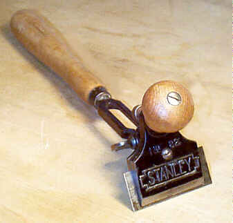 Another scraper, which
sorta looks like the #70 box scraper. It has a long,
turned wooden handle,
which has a pivoting portion to hold the scraper blade.
This pivoting portion
has a turned knob, which is gripped in the other hand, and
a clamping mechanism
to secure the blade. The advantage of a scraper of this
design is that the
blade can be adjustable to different angles, and the
workman could bear down on
it better than other designs.
Another scraper, which
sorta looks like the #70 box scraper. It has a long,
turned wooden handle,
which has a pivoting portion to hold the scraper blade.
This pivoting portion
has a turned knob, which is gripped in the other hand, and
a clamping mechanism
to secure the blade. The advantage of a scraper of this
design is that the
blade can be adjustable to different angles, and the
workman could bear down on
it better than other designs.
There are two designs of this tool. The first model
has the lever cap screw
on the face opposite the turned knob. This model uses a
simple thumb screw that
passes through a slotted arc-shaped piece to secure the
blade at one of four
angles (there are four notches cut into the slot of the
arc-shaped part).
During the early 1930's, the tool was redesigned to take
advantage of a new
patent that called for notches cut into two opposing mating
surfaces. These
notches don't allow the 'infinite' freedom of the blade's
position either since
the notches in the pivotting assembly slip into each other
in a predetermined
fashion. On the positive side, these notches offer greater
'holding' power and
won't slip under a heavy load like the previous design can.
The redesign also
called for a spring, located behind the front knob on the
opposite face, to cushion
the blade and eliminate chatter. To accomodate these two
changes, the turned
knob was moved to a position slight lower on the clamping
mechanism and the
lever cap screw was repositioned to the same face as the
turned knob.
Because of the way the blade is clamped in place, and
because the clamping
mechanism is unencumbered to either side, the tool is
capable of holding blades
of any width, making it useful for scraping into weird
locations that aren't
accessible by the other scrapers. Paint scraper blades, in
the shape of a broad
and flattened U were also provided for this piece later in
its production.
The handle and knob are maple, and on the earliest
examples they have a
clear finish on them. Starting in the early 1940's, the
finish became a deep
maroon. A ferrule is situated at the juncture of the handle
and where the cast
iron 'tang' is inserted into it. The cast iron portion of
the plane is
japanned, while the thumb screws are nickel plated.
#83 Wood scraper, 9 1/2"L, 3"W (4", 1914 on (3 7/8", 1925 on), 1 1/2lbs, 1897-1934.
This is one of those strange tools that makes you wonder who would ever design such a thing, let alone manufacture it. The obvious answer, in case you're in suspense, is Justus Traut and The Stanley Rule and Level Co.
It's basically a rectangular casting that accepts a
caster-like roller, and
has a turned wooden handle screwed onto it. The handle,
which is maple or beech
with a clear finish on it, is shaped like a dumbbell but
with sausage-shaped
ends that are gripped in each hand. Between the two
'sausages' is a cylindrical
portion through which a countersunk screw fits into the main
casting. The
handle can be removed to permit the scraper to work into odd
corners.
 The main casting is
nickel plated, and has 3 thumb screws threaded into it.
There are two screws
that hold the blade in place; the blade slips into two
slit-like slots cut into
respective swellings of the main casting. These areas can
crack since they
carry much of the strain placed upon the tool during its
use; look about them
for any repairs or hairline cracks. The earliest examples
have the patent date
proudly embossed above the handle.
The main casting is
nickel plated, and has 3 thumb screws threaded into it.
There are two screws
that hold the blade in place; the blade slips into two
slit-like slots cut into
respective swellings of the main casting. These areas can
crack since they
carry much of the strain placed upon the tool during its
use; look about them
for any repairs or hairline cracks. The earliest examples
have the patent date
proudly embossed above the handle.
Between these two swellings is a conical portion of
the casting which rises
above the rest of the main casting. This conical portion has
a vertical hole
drilled through it and accepts a sliding post that in turn
terminates with a
roller. The sliding post is positioned within the conical
portion via a
thumbscrew. This area of the main casting also is
susceptible to damage since
it, too, carries a great amount of strain during use; a
close scrutiny about it
is wise.
The roller itself is maple or beech and it, along
with its captive post, is
usually missing in action. The wooden roller is sometimes
found cracked or with
missing chunks out of it. The roller came in two widths -
one measuring around
5/8" in length and the other about 1" in length. The post
that
carries the roller has a flat milled on it so that the
thumbscrew can lock it
in place better and so that the roller aligns properly
relative to the blade;
if the roller were allowed to be positioned so that its axis
isn't parallel to
the face of the blade, the tool would want to wander in a
direction you don't
want it to go.
So, what's the supposed appeal of this contraption?
The presence of the
roller eliminates the strain placed upon the wrists and
hands during the tool's
use. Also, the pitch of the blade can be customized simply
by sliding the post
up or down through the main casting; moving the roller
closer to the main casting
pitches the blade at a steeper angle. The roller can be
positioned so that the
scraper is oriented to make inoperable. The tool can be
pulled or pushed. You
want to make sure that the roller precedes the blade so it
doesn't leave any
track marks on the wood; i.e., the tool is oriented so that
the roller is away
from you.
Forget this dumb tool and get a real scraper, like a
#12 or #112,
instead. It does have a plus side, however - it's the
widest of all the
Stanley-made scrapers since it can accept a 4" wide blade,
but the blades
are normally long gone in these things. A #12 blade will not fit into
this tool; it's too wide
and too thick to slip into the slits cut for it in the
main casting. You need a
thinner iron to work in this tool.
#85 Cabinet maker's scraper plane, 8"L, 2"W, 2 5/8lbs, 1905-1934. *
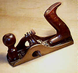 This is a scraper plane
with a rabbet mouth and tilting knob and tote. It is
designed to work into
corners, where the knob and tote are tilted to prevent
smashing your knuckles,
an application that every woodworker does at least 3 times
daily.
This is a scraper plane
with a rabbet mouth and tilting knob and tote. It is
designed to work into
corners, where the knob and tote are tilted to prevent
smashing your knuckles,
an application that every woodworker does at least 3 times
daily.
The plane resembles a conventional bench rabbet, like
the #10 1/2, but
the frog design is totally different. It is a two piece
construction, where a
captive pivoting lever cap is pinned to another L-shaped
piece, which is in
turn screwed to the bottom casting much like the frog of
the common Bailey
bench plane is. The blade is secured into the frog using a
thumb screw, as
might be guessed, but it does so in a manner opposite what
is common on other
planes. The thumb screw is not on the pivoting lever cap
but is located behind
the cutter. As the thumb screw is tightened, it throws the
top of the cutter
forward toward the top of the lever cap, causing the lever
cap to pivot,
ultimately placing pressure at the bottom of the lever cap
over the width of
the cutter. The plane has the lever cap screw arranged
thus since there isn't
enough room to accomodate it freely due to the fact that
the frog leans toward
the knob; there isn't sufficient clearance between frog
and knob. Look for any
signs of repair or breakage where the lever cap is pinned
to the L-shaped
piece.
The frog can be adjusted forward or backward somewhat
to regulate the
opening of the mouth. This is done manually, by backing off
the pressure of the
two screws, which hold the frog to the bottom casting.
Between these two
screws, and a bit behind them, is another smaller set screw.
This screw can be
turned to adjust slightly the blade's pitch. If it is set
too much, and too
much presure is applied to the frog's other two screws,
cracking of the frog's
casting can occur about the set screw. Check this area very
carefully, if
you're to purchase one of these.
 The tilting rosewood
knob
and tote are susceptible to cracks and breakage about their
bottoms. Both are
secured in place like the #10
1/4's
are. Look both the knob and tote over
carefully for any signs of damage, repair, or replacement.
You can't salvage
replacement knobs and totes from any old bench plane - you
have to snarf them
from a broken #85
or #10 1/4,
both of which aren't found under rocks in any part of our
great and wealthy
country.
The tilting rosewood
knob
and tote are susceptible to cracks and breakage about their
bottoms. Both are
secured in place like the #10
1/4's
are. Look both the knob and tote over
carefully for any signs of damage, repair, or replacement.
You can't salvage
replacement knobs and totes from any old bench plane - you
have to snarf them
from a broken #85
or #10 1/4,
both of which aren't found under rocks in any part of our
great and wealthy
country.
During use, the blade springs backward, which then
allows the shavings to
escape. The tool is pushed and gripped like a regular bench
plane. Despite all
its clever features, it wasn't very popular, and is now a
very collectible
tool. The blade is unique to this plane as its width
increases (over its
length) to fill the rabbet mouth. There isn't a lot of
useable meat on these
blades, and they are often long gone having been used up in
a day or two. The
most desireable planes will have the Stanley logo stamped on
the cutter, which
gives the collectors a warm and fuzzy feeling over its
originality.
#87 Cabinet maker's scraper plane, 8"L, 2"W, 2 1/2lbs, 1905-1917. *
This is a very rare plane, which never was popular due to the other cheaper and more versatile scrapers Stanley offered. This one is very much like the #85 in appearance, except that it doesn't have a rabbet mouth, nor does it have the tilting knob and tote. On this model, the knob and tote are secured to the bottom casting with a brass slotted screw and a threaded rod. Other than that, the plane is identical to the #85 in every regard, and suffers the same possibility of damage that that one does. The plane was practically DOA with the ballsy #112 doing the same duty, and much better at that, than this one does. The mind goes apoplectic when pondering why Stanley didn't offer a corrugated version of this one - wow, imagine what one would be worth if they had?
[ START ] |
[ PREV ] | [ NEXT
] | [ END ]
[ HOME
]
Copyright
(c) 1998-2012 by Patrick A. Leach. All Rights Reserved.
No part may be
reproduced by any means without the express written
permission of the author.