The Superior Works: Patrick's Blood and Gore Planes #45 - #A45
#45 Combination plane 10 1/2"L (11 1/2" 1897 on), various widths (see below), 9 1/2lbs, 1884-1962.
 This
is Stanley's most famous and popular combination plane. A
combination plane is
one that can be fitted with different irons, or cutters, as
Stanley called
them, and be adjusted for a particular cut. The basic #45 can groove, rabbet, dado,
match (tongue and groove),
bead (edge and center), slit, and cut sash. With the
special bottoms and
cutters, which were purchased separately from the basic
model, the plane can do
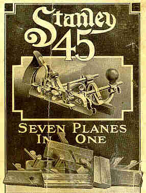
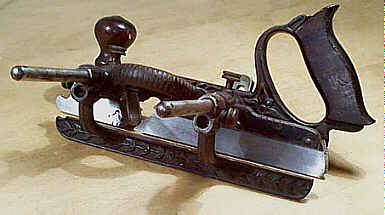
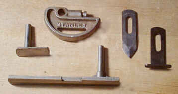
simple moldings, nosing, reeding, and fluting. The images
that follow (in
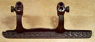
order) show a catalog cover, a Type 1 model, a close-up of
the Type 1's fence,
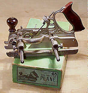
a Type 5 in its original rare green box, the commonly
missing parts, the two
style of cam rests, and an earlier wooden carrier for all
the cutters.
This
is Stanley's most famous and popular combination plane. A
combination plane is
one that can be fitted with different irons, or cutters, as
Stanley called
them, and be adjusted for a particular cut. The basic #45 can groove, rabbet, dado,
match (tongue and groove),
bead (edge and center), slit, and cut sash. With the
special bottoms and
cutters, which were purchased separately from the basic
model, the plane can do
simple moldings, nosing, reeding, and fluting. The images
that follow (in
order) show a catalog cover, a Type 1 model, a close-up of
the Type 1's fence,
a Type 5 in its original rare green box, the commonly
missing parts, the two
style of cam rests, and an earlier wooden carrier for all
the cutters.
It was inevitable that planes of this design and
function would be
introduced for several reasons: the wooden plane business
was on its last leg,
technological advances in casting and design accelerated,
and the reduced space
and weight (in total) of them over the wooden planes they
replaced.
Stanley didn't originate the idea of combination
planes, but they were the
one to popularize them and were the last one to be standing
in the combination
slugfest. Would be contenders, such as Siegley, Fales,
and Walker were all left in Stanley's dust during the mad
rush to build a
better combination plane.
I hate them. There, I said it right off. Why? I find
them to be tempermental
beasts, where it seems just as much time is spent setting
them up as there is
when using them (obviously this isn't the case when sticking
10's or 100's of
feet of stuff). Then there is their problem with tearout;
stock selection is
very important to use them satisfactorily. Unlike the wooden
planes that the #45
replaces, there is no complete bearing surface
ahead of the cutter. Instead, two narrow skates 'serve'
that function. As a
consequence, the majority of the iron has a mouth that is,
in essence,
infinitely wide, which, naturally, makes for suboptimal
results. Now, the
wooden planes (that the #45
replaces) aren't known for the tightness of their mouths,
and as a result will
tearout on grain changes. But, I've found the amount of
tearout to be far less
than that of a #45. Beads are
the worst performer of the #45,
and I'd rather use 'lectrical tools to make sash than to
use this plane for the
same.
One other thing I dislike about combination planes is
that they are heavy,
much more so than the wooden planes. Wooden planes, because
they are dedicated
to a particular task, only need to have their irons set and
then it's off to
the planing. Oh, I thought of something else bad about the #45 - there are too many parts
that can get lost or
broken, which any owner of a #45
is all too familiar.
My personal opinion aside, these planes are useful
for many people. Those
folks who do not have the space for, nor the chance to
acquire, the wooden
planes the #45
replaces find them very
useful. The #45 also is cheaper
than having to buy all the other planes it replaces. If I
had to use the plane
(like if a gun was stuck to my head, or something like
that), I'd only do so
for making reeds. It does a respectable job of that,
provided the wood's grain
is even, and you have copious scraps of wood about to test
the plane's setting
with each adjustment. It also ploughs about as well as any
wooden plane, but
that's because wooden ploughs, like the #45, do not have a complete
bearing surface ahead of
the cutter.
What follows is a list of all the parts found on a
complete #45. Some
of the parts were introduced later during the
plane's lifetime. Like everything Stanley produced, the
parts were numbered for
ordering and inventory control. None of the numbers that
follow appear on the
parts.
- #1 Set of cutters (explained later).
- #16 Main stock - the part with the rosewood tote and a fixed skate.
- #23 Cutter bolt - wingnut-activated bolt to secure the cutter.
- #24 Cutter bolt wignut - fixed to the cutter bolt.
- #25 Cutter bolt clip and screw - secured to right side of the main stock to prevent the bolt from working free.
- #27 Cutter bolt adjustment screw - the screw that engages the cutter with a pin on the bottom of it.
- #28 Cutter bolt adjustment wheel - the wheel held captive in the main stock through which the adjustment screw passes; both #27 and #28 are used to set the cutter's depth.
- #29 Arm set screws - the pair of screws that fix the arms to the main stock.
- #30 Sliding section - the leftmost skate that is set to the cutter's width; it rides on two arms.
- #50 Left fence - the adjustable fence that regulates how far onto the wood the plane makes its cuts; it is secured to the arms with screws and has a rosewood strip screwed to it.
- #60 Long arms - a pair of round arms onto which parts are fixed to control the plane's cut; they're around 8 1/4".
- #61 Short arms - like #60, only shorter; around 4 1/2" long.
- #70 Adjustable depth gauge - an L-shaped threaded gauge that is fixed to the main stock.
- #71 Adjustable depth gauge nut - the knurled nut that regulates the setting of #70.
- #73 Adjustable beading stop - the L-shaped gauge that fits into the sliding section; a screw like #29 secures it.
- #75 Slitting cutter stop - a stamped metal stop to control the slitting cutter's depth; it is located near the tote.
- #76 Thumb screw - along with a washer, is used to hold the slitting cutter and its stop.
- #80 Cam rest - a D-shaped stop that is fixed to the arms to give additional support when planing; this was added ca. 1905.
- #81 Cam rest set screw - the screw used to secure the cam rest.
- #85 Spurs with screws - the spurs that are fixed to the skates, forward of the cutter; there are two - one on each skate.
Click here for an exploded catalog drawing of the plane (ca. 1935).
 There is a rosewood
knob
that is either attached to the main stock (on the earlier
models) with a threaded
post and a cylindrical slotted screw or is attached to the
fence's main casting
(on the later models). This knob, located toward the front
of the plane, is
provided so that sufficient lateral pressure can be applied
to the plane,
keeping it bearing against the edge of the stock being
worked. The earlier
knobs are prone to splitting about their base and are rather
fragile. Stanley
later moved the knob to the left fence. In this
configuration the knob screws
directly to a threaded boss on the fence's casting.
Sometimes, the knob strips
and won't stay fastened to the fence. Check for this damage
by unscrewing the
knob from the casting.
There is a rosewood
knob
that is either attached to the main stock (on the earlier
models) with a threaded
post and a cylindrical slotted screw or is attached to the
fence's main casting
(on the later models). This knob, located toward the front
of the plane, is
provided so that sufficient lateral pressure can be applied
to the plane,
keeping it bearing against the edge of the stock being
worked. The earlier
knobs are prone to splitting about their base and are rather
fragile. Stanley
later moved the knob to the left fence. In this
configuration the knob screws
directly to a threaded boss on the fence's casting.
Sometimes, the knob strips
and won't stay fastened to the fence. Check for this damage
by unscrewing the
knob from the casting.
Surprisingly, many of the fences for these planes can
be found damaged
and/or repaired. Often, the slender portion of the fence's
casting, where it
curves downward from the arms, cracks. These cracks render
the plane useless,
and many guys had the cracks welded. Look all around the
fence for any signs of
repair. On those models that have a rosewood face to the
fence you can find the
rosewood all banged up or split. This is easy to fix with
another piece of
wood, but finding Brazilian rosewood, what Stanley used on
them, might prove
difficult. And while on the subject of the fence, the fence
can be turned 180
degrees (end-to-end) so that the rosewood is on the outside
and the knob is
over the rear arm. This feature allows you to work farther
into the wood by
another 2", which can be handy when doing center beads,
because the
fence's arms are curved.
 On the main stock
check
that the cutter adjustment mechanism (those later models
that have them) works
easily and that the area of casting that holds it isn't
cracked. The cutter
bolt can sometimes not pop free when the cutter bolt is
backed off. If this
happens, disassemble the entire cutter securing parts and
clean them. On the
models that have the cutter bolt clip, check that neither of
the
"tines" is gone. Check that the spur is still present on the
right
side of the skate, and while you're at it check the sliding
section's left side
of the skate for its spur. Both these spurs mount flush to
the surface of their
respective skates with a countersunk screw.
On the main stock
check
that the cutter adjustment mechanism (those later models
that have them) works
easily and that the area of casting that holds it isn't
cracked. The cutter
bolt can sometimes not pop free when the cutter bolt is
backed off. If this
happens, disassemble the entire cutter securing parts and
clean them. On the
models that have the cutter bolt clip, check that neither of
the
"tines" is gone. Check that the spur is still present on the
right
side of the skate, and while you're at it check the sliding
section's left side
of the skate for its spur. Both these spurs mount flush to
the surface of their
respective skates with a countersunk screw.
The beading gauge, the long depth stop-like piece
with a 'rabbet' milled in
it, is used to bead matched boards. Matched boards are
nothing but boards that
mate with each using a tongue and groove joint, and were all
the rage during
the late 1800's to the first quarter of the 20th century.
The boards are
oriented vertically and more often than not decorated with a
bead on the tongue
side of the board. To make matched boards, you cut the
grooves and tongues on
all the stock using the appropriate cutters for those tasks.
The beading gauge
is then fit into the forward hole of the sliding section,
with the beading
gauge's rabbet fitting snugly against the sliding section's
skate. The sliding
section is then positioned as it normally is for side
beading, with the beading
stop now functioning as the fence, riding above the tongue.
The regular fence
is not used for this operation. Beading gauges on the
earliest models are
japanned, and were later nickel plated when the rest of the
plane received the
same treatment.
 The plane underwent
several modifications to its design during its long period
of production. The
most noticeable difference between the early and late models
is the plane's
finish. The earliest are japanned, while the later are
nickel plated. It would
take several pages to describe all the changes made to the
plane over its long
period of production. However, a few major changes are noted
to help you date
your plane or to point out any incompatibilities amongst the
models.
The plane underwent
several modifications to its design during its long period
of production. The
most noticeable difference between the early and late models
is the plane's
finish. The earliest are japanned, while the later are
nickel plated. It would
take several pages to describe all the changes made to the
plane over its long
period of production. However, a few major changes are noted
to help you date
your plane or to point out any incompatibilities amongst the
models.
The oldest models have their arms threaded into the
main stock, whereas
those produced after ca. 1900 slide through the main stock.
The castings of the
main stock and the fence are embossed with floral motifs and
are japanned.
Starting ca. 1890, the castings, while still cast with
floral (on the main
stock) motifs, are nickel plated. Starting ca. 1895, the
cutter adjustment
screw was added just forward of the handle casting, a strip
of rosewood was
added to the inside edge of the iron fence, and the rosewood
knob was moved
from the main stock to the fence. Starting ca. 1910, all
floral motifs were
removed from the castings and replaced with a stippled
pattern. From here on,
the plane remained pretty much unchanged, except for
variations in the
trademarks and some subtle casting changes.
 The screws used to
secure the parts in position also offer a clue about the
plane's date. The
earliest are unslotted brass screws. For a few years
afterward, the planes came
equipped with slotted brass screws. Starting around 1890,
the slotted screws
were nickel plated and remained that way until ca. 1900 when
the screws were replaced
with flattened thumbscrews.
The screws used to
secure the parts in position also offer a clue about the
plane's date. The
earliest are unslotted brass screws. For a few years
afterward, the planes came
equipped with slotted brass screws. Starting around 1890,
the slotted screws
were nickel plated and remained that way until ca. 1900 when
the screws were replaced
with flattened thumbscrews.
For grooving, the sliding section is normally not
used with the narrower
cutters - cutters around 1/4" and less can be used without
the sliding
section since they don't suffer flexing along their left
edge like the wider
cutters do. When cutting wide grooves or wide rabbets, the
sliding section is
mandatory as it lends support to the wider cutters. If you
note that the wider
cutters are giving you fits, and the sliding section is
situated to the
leftmost edge of the cutter, you might want to move the
sliding section closer
to the main stock a bit as this tends to stabilize the
cutter by preventing
flexing about the middle of the cutter.
The sliding section and the fence tend to bind as
they are moved about on
the arms. The jumpy movement of them during setup often
makes for a tough time
of getting the accuracy you desire. This can be a real pain
in the arse, and
Stanley took steps to address it. Starting around 1915, a
fine adjusting screw
was provided for in the fence. A single knurled thumb screw
can tweak the
rosewood strip to set how far from the board's edge the
plane works, which is a
real benefit when trying to cut a groove, a bead, or
whatever at a precise
location. Because of this feature, planes made during this
era and later are
more in demand (by users) than the earlier models are. One
thing to check on
planes with this kind of fence is the presence of a locking
thumb screw tapped
into the lower front part of the casting. This thumb screw
locks the rosewood strip
in the position you set. Many planes are missing this thumb
screw.
Many folks have no idea what the slitting cutter is
used for, nor are they
appreciative of what a clever and powerful little gizmo this
thing is. It,
along with its pressed steel depth gauge, are usually MIA,
but replacements are
fairly easy to find. Once you use the slitting cutter,
you'll realize just how
cool it is, and your fingers will forever stay attached to
your hands since you
won't have to resort to that dangerous spinning blade that
sticks up from a
cast iron table to rip thin strips of wood. The slitting
cutter and depth stop
are attached to the plane in a milled area located at the
right rear of the
plane, just forward of the handle (earlier models attach the
slitting cutter over
the extra long rear arm). The fence is used to position how
far into the wood
the slitting cutter does its slitting thing, and the depth
stop controls how
deeply into the wood the slitter goes. With the slitting
cutter extended below
the stop, all it takes is a few passes to cut a thin strip
off a larger piece
of wood (if the wood is thick, you usually run the slitter
from both faces).
This function is very useful for slicing beads from the wood
so that you can
use them to decorate whatever your mind can imagine.
 The cam rest, first
added
during the very early 1900's, is a clever and useful device,
but only when you
need it, which isn't very often. If you want to cut a bead,
or anything else
for that matter, way in the middle of a wide board, the
distance between the
fence and the main stock is rather great. In this
configuration, the plane is
apt to rock laterally making it somewhat difficult to use.
The cam rest solves
this problem by providing an intermediate bearing surface
between the fence and
the main stock. The cam rest is positioned between the two
parts, roughly
equidistant from each. There is one slight gotcha with the
cam rest - it
prevents the plane from cutting deeper into the wood on
successive passes since
it behaves just like a depth stop. You solve this problem by
pivotting the cam
rest back toward you just a hair and then taking the next
pass with the plane;
the cam rest is an eccentric shape making it possible to
adjust its depth
finely. If you set the cam rest's thumb screw so that it's
tight enough to
resist movement during use, but not tight enough that you
can force it to move
with your brute strength, you can avoid the hassle of
loosening, positioning,
and tightening it between successive passes.
The cam rest, first
added
during the very early 1900's, is a clever and useful device,
but only when you
need it, which isn't very often. If you want to cut a bead,
or anything else
for that matter, way in the middle of a wide board, the
distance between the
fence and the main stock is rather great. In this
configuration, the plane is
apt to rock laterally making it somewhat difficult to use.
The cam rest solves
this problem by providing an intermediate bearing surface
between the fence and
the main stock. The cam rest is positioned between the two
parts, roughly
equidistant from each. There is one slight gotcha with the
cam rest - it
prevents the plane from cutting deeper into the wood on
successive passes since
it behaves just like a depth stop. You solve this problem by
pivotting the cam
rest back toward you just a hair and then taking the next
pass with the plane;
the cam rest is an eccentric shape making it possible to
adjust its depth
finely. If you set the cam rest's thumb screw so that it's
tight enough to
resist movement during use, but not tight enough that you
can force it to move
with your brute strength, you can avoid the hassle of
loosening, positioning,
and tightening it between successive passes.
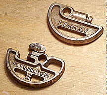
There are two styles of cam rests. The first style
has a thumb screw that
sticks up from it. This style has a slit cut into the cam
rest's casting so
that the casting pinches the rod as the thumb screw is
tightened. This style
proved too costly to manufacture and was quickly redesigned
to the form most
commonly found with the plane. This new style has a set
screw that's oriented
horizontally into a solid (no slit) casting. The set screw
pushes a rod that's
inserted into the cam stop. This rod then exerts pressure
onto the arm and
locks the cam rest in place. A lot of these later cam rests
are missing their
internal rod. If it's missing, it's an easy thing to replace
Now for all those blasted cutters. Here again, some
of the cutters were
introduced later during the plane's lifetime. However, there
is a core set of
them that were offered with the plane during its entire
production. The
following tables show all the "standard" cutters that were
offered
with the plane, and the year that they were first offered
(the year that they
were first noted in literature).
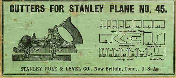
Cutters First Offered in 1884
|
beading |
1/8", 3/16", 1/4", 5/16", 3/8", 7/16", 1/2" |
|
ploughing |
1/8", 3/16", 1/4", 5/16", 3/8", 7/16", 1/2", 5/8" |
|
slitting |
V-shaped |
|
tonguing |
1/4" |
Cutters First Offered in 1897
|
ploughing |
3/4" |
|
sash |
1 1/2" (made optional in 1914) |
Cutter First Offered in 1914
|
fillister |
1 1/4" |
Cutter First Offered in 1919
|
plough |
13/16" |
Click here for a catalog drawing of the standard cutters.
The cutters came in wooden boxes (the earlier models) or cardboard boxes (the later models). The cutters can be used in the #55, but the reverse is not true for some of the cutters of the #55. Some of the #55's complex profiles need an additional skate to work, which the #45 doesn't have.
Some other cautions about the cutters need
mentioning. The earliest cutters
do not have the cutout on them to engage the pin on the
cutter bolt adjustment
screw, so these older cutters cannot be used on those models
of the #45 that
have the adjustment screw, unless you want to
make the cutouts yourself. The matching cutter, the one
that cuts the tongue,
has a small and adjustable stop that fits into the cutter.
This stop regulates
how long a tongue is cut with the tool since it's
impractical to use the normal
depth stop when cutting tongues; there isn't any place for
the normal depth
stop to make contact and stop the plane from cutting. Many
of these matching
cutters are missing their depth stops.
 You might notice the
addition of the odd size of 13/16" for the ploughing (in
1919) and
matching (in 1925). This strange dimension also made its
debut in 1919 for the #39
13/16. Why
this particular dimension all of a sudden appeared in the
Stanley offerings is
unknown to me. Some wooden plane manufacturers offered
wooden dado planes in
the 13/16" width, back during the last quarter of the 19th
century. There
must have been some trade that required this dimension, or
perhaps 13/16"
became the standard thickness for wood much like 3/4" is
our standard
today. However, if it was a standard back then, there
certainly isn't the
expected number of planes sized to work that dimension out
there.
You might notice the
addition of the odd size of 13/16" for the ploughing (in
1919) and
matching (in 1925). This strange dimension also made its
debut in 1919 for the #39
13/16. Why
this particular dimension all of a sudden appeared in the
Stanley offerings is
unknown to me. Some wooden plane manufacturers offered
wooden dado planes in
the 13/16" width, back during the last quarter of the 19th
century. There
must have been some trade that required this dimension, or
perhaps 13/16"
became the standard thickness for wood much like 3/4" is
our standard
today. However, if it was a standard back then, there
certainly isn't the
expected number of planes sized to work that dimension out
there.
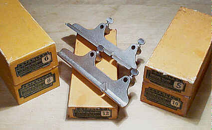
The plane can also be equipped with extra bottoms,
that were originally
purchased as options. These bottoms are used to cut hollows
and rounds, or a
nosing. The bottoms are dedicated to a particular size, and
come equipped with
a cutter of the appropriate size. Each bottom fits onto the
arms, and mates
with the skate of the main stock. The sliding section isn't
used when the extra
bottoms are. The earliest bottoms are japanned and have no
number cast into
them; they use slotted brass screws to secure them to the
arms. The later ones
have a matte nickeled finish for their surface and a number
cast into them;
they use nickeled slotted screws or thumb screws to fasten
them to the arms.
The nickel plated bottoms can be found with their respective
part numbers
embossed on them. The following table lists the extra
bottoms and the years
they were offered.
Extra Bottoms Offered from 1885 - 1942
|
#6H & #6R |
3/4" hollow & 3/4" round |
|
#8H & #8R |
1" hollow & 1" round |
|
#10H & #10R |
1 1/4" hollow & 1 1/4" round |
|
#12H & #12R |
1 1/2" hollow & 1 1/2" round |
Extra Bottom Offered from 1892 - 1942
|
#5N |
1 1/4" nosing |
Click
here for a catalog drawing of the bottoms.
There were also other optional cutters that were
offered. They do not need
the auxiliary bottoms, like the hollows and rounds and the
nosing tool. They
are secured into the plane like any of the basic cutters
are. A complete set of
these cutters, in their original boxes, is more valuable
than the complete
plane is. The following table lists the optional cutters and
when they were
first offered.
Optional Cutters First Offered in 1889
|
reeding (ordered in 2, 3, 4, and 5 reeds) |
1/8", 3/16", 1/4" |
Optional Cutters First Offered in 1914
|
sash |
1 1/2" (rabbet on left side of cutter) |
|
matching |
3/16" |
|
beading |
5/8", 3/4" |
|
fluting |
3/16", 1/4", 5/16", 3/8", 7/16", 1/2", 5/8", 3/4" |
Click
here for a catalog drawing of special cutters.
All of the cutters have a part number associated with
them. This number is
often stamped on the face of the cutter, up near the heel.
The same numbering
system that was used on the #55's cutters (which see, if
you're at all interested
in that minutia) was also used for the #45.
#A45 Combination plane 10 1/2"L, various widths (see above, I don't feel like typing the cutter junk again), ~5lbs, 1926-1934. *
This was another one of Stanley's boneheaded ideas as far as popularity is concerned. However, this is one plane where it makes some sense to have the plane as light as possible. The public didn't buy it, and the plane is very rare.
Every part of the plane that fastens onto the rods -
the main stock, the
sliding section, the fence, and, yes, the cam rest - are
made of that perfect
metal for tools, aluminum. The plane is fitted with a
rosewood handle and a
rosewood fence, just like those found on the cast iron
model.
There are some examples of this plane that have iron
cam rests, and I'm told
that they are original to the plane. I've had the misfortune
of owning only one
of these aluminum monstrosities, and its cam rest was
aluminum. You be the
judge whether the cam rest should or shouldn't be aluminum,
but keep in mind
that there are reproduction aluminum cam rests out there.
If you're missing one of these parts, you can step to
the rear of the
"Need parts for my #45" line. Do allow plenty of space between you and
the person in
front of you to permit newcomers to cut in line, however,
since Shelton planes
will be a hot collectible by the time you locate a proper
aluminum replacement
part for your plane.
Most of the models have "A45" cast into them. There
are a few that
do not, and just have "45" only cast into them. The Stanley
Operating
Committee voted in 1915 the authorization to produce the #45 in aluminum and the quickest
means to the end was
to use the same patterns as those of the cast iron model,
which don't have the
"A" prefix for them. The plane was offered earlier than
the 1926 year
listed above, but that year is the earliest catalog
reference. Stanley did have
the habit of introducing new planes with little fanfare;
i.e., dedicated
pamphlets or advertising in magazines before the plane
made it into their
catalogs, possibly to spare them any embarassment should
the plane prove to be
a miserable flop. Nah, check that. Nothing stopped Stanley
from making stupid
planes, with the nightmares-come-true #193 "fibrebored" planes as proof
of that.
Stanley used different boxes to pack the plane. Some
of the boxes are just
the regular hard cardboard #45 boxes with a small printed
label that reads
"ALUMINUM" pasted on the larger green label. Other boxes
have labels
that have "A45" printed on them.
Aluminum isn't a very forgiving material. Check the
plane carefully for
cracks, breaks, bends, dings, etc. Don't bother looking for
rust or peeling
nickel plating (on the larger castings) - you won't find
either on this one.
[ START ] |
[ PREV ] | [ NEXT
] | [ END ]
[ HOME
]
Copyright
(c) 1998-2012 by Patrick A. Leach. All Rights Reserved.
No part may be
reproduced by any means without the express written
permission of the author.