The Superior Works: Patrick's Blood and Gore Planes #55 - #57
#55 Universal Combination Plane 10"L, (various widths), 15 1/4lbs, 1897-1962.
 Bought
it. Used it. Hated it.
Sold it.
Bought
it. Used it. Hated it.
Sold it.
The Great Zeus Himself thought His sentence of
Prometheus to be the ultimate
punishment for mankind, and throughout the millenia it was.
That is, until the
year 1897 when Messrs. Justus Traut and Edmund Schade
devised a torture that
knew no bounds betwixt Gods and mortals. We should all be so
lucky to be
chained to a rock and have our livers eaten daily by an
organ-hungry raptor
than to suffer the agony of this contraption. Even the
Chinese would have
gladly abandoned their infamous drip, drip, drip of water to
the forehead had
they been on Stanley's favored nations tradelist. If there
can be a ball and
chain of planes, this is it, baby.
Down in Australia this chunk of metal has been used
as a doorstop (no lie).
Here in America, it's been used as a woodworking tool. Now,
you tell me which
nation is more civilized? And since I'm on a roll slamming
this tool, why stop
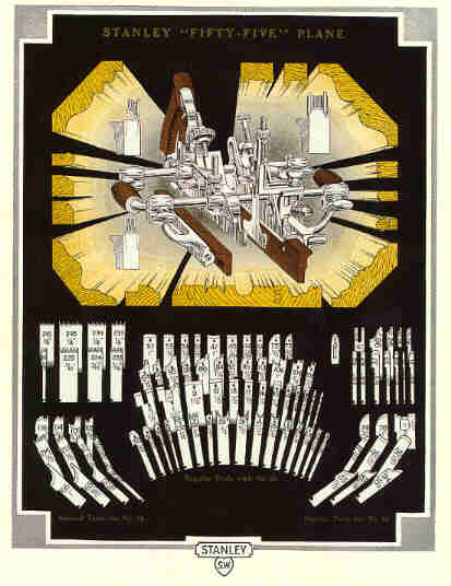
here? Stanley advertised that the #55
was "A planing mill in itself." More like "A paining kill
in
itself" is a befitting slogan for the tool. Over in
Greece, sponge divers
tie these things around their waists as ballast to get
them to the briney
depths sooner. In India, swamis position a few dozen of
them in a rectangular
fashion and then have a snooze atop them.
This plane certainly is one clever chunk of metal
design. With the success
of the #45,
and other Stanley combination planes, it wasn't long
before Stanley produced
this. The timing was perfect for its introduction, since
metal planes of all
sorts had proliferated for some 30 years prior, which
meant there would be little
objection from those guys trained in the "old school"
(they were
dead, dying, or feeble), and the wooden plane business was
all but dead. Also,
what pitiful few moldings that were fashionable at the
time were simple
profiles, which the #55 could
handle. Had the complex Grecian profiles still been
popular, this plane might
never gotten off the ground.
Put simply, it's a temperamental monster that
requires much fussing with in
order for it to work well. Were you in the need to make a
short run of molding,
it may be a suitable alternative to a wooden plane. However,
for any profile
that you plan to stick over and over, a dedicated wooden
plane is preferable.
Why? Wooden molding planes are self-regulating; i.e., they
have a fixed fence,
a fixed profile, and a fixed depth stop. The #55 also has these three necessities, but none of
them are fixed; they are
all variable and require a great amount of skill/patience
to get them to work
perfectly. This fact doesn't rear its ugly head so much
when sticking a profile
with a single cutter (say an ogee), but it surely does
when using a combination
of cutters to stick a profile that normally can be found
in a wooden plane. It
also suffers the same deficiency that the #45 does regarding stock selection
- the wood must be
even-grained to minimize tearout, since there is no mouth,
in the true sense of
the word, on this plane.
Stanley loved to claim that this plane "will do a
greater variety of
work than can be done with a full line of so called Fancy
Planes." This,
as any person knowledgable of wooden planes knows, is utter
propaganda. What
this same person recognizes is the truth to Stanley's claim
that the plane is
more compact, and thus lighter, than a full line of "Fancy
Planes,"
but big deal. Unless you're a mobile workman, these facts
are meaningless. For
an operating cabinetshop, there's plenty of room for all the
"Fancy
Planes." What Stanley didn't say is that their metal beast,
with one
cutter in it, weighs a minimum of 7 3/4 lbs. There is no
wooden molding plane
(other than a wider than usual cornice plane, of a profile
the #55 couldn't
produce anyway) that weighs that much.
The plane is pretty much the same as the #45. It goes a bit further by
facilitating cutters that
require irregular bearing points across their width. For
example, a simple bead
can be cut with a #45 since both sides of the
profile are in the same
geometric plane. Two skates, one at each side of the bead
are positioned; one
skate, on the main stock is fixed, and the other, part of
the sliding section,
is secured to the arms. This same principle is used on a
more complex profile,
like an ogee; the cutter is fixed in the main stock, and
the sliding section is
positioned to the other side of the cutter. Problem is,
this part of of the
cutter is incapable of cutting since the skate, being only
laterally adjustable
and not vertically adjustable, precludes it from making
contact with the wood.
To address this deficiency, the #55
has a vertically adjustable sliding section, which allows
the skate to be moved
up or down to expose the leftmost (to the main stock)
portion of an irregular
cutter. A long threaded rod accomplishes this. Also
attached to the sliding
section is an auxiliary skate, or bottom, which is
likewise adjustable both
vertically and laterally. This auxiliary bottom is used as
extra support to
prevent the cutter from gouging into the work (hey, wooden
molding planes don't
do that). Where this bottom is used is on profiles like
ogees, or compositions
using the hollows and rounds cutters.
The plane can only hold one cutter at a time. Its
position from the the
board's edge is regulated by an adjustable fence. There are
two of these fences,
which can be used on either side of the plane. The fence
that's normally used
on the left side of the plane comes with an adjustable face
(made of rosewood),
which can be tilted up to 45 degrees so that chamfers can be
worked. This same
face also has a fine adjustment mechanism to allow greater
accuracy when
positioning the cut's location on the board (the fact that
the plane has this
feature ought to give an indication that setting the plane
up is a task unto
itself).
The right fence also has a rosewood face that can be
titled up to 45
degrees, but it uses conventional wood screws to do that. It
doesn't have the
fine adjustment that the left fence does. Instead, this
fence has a flat
outside (the side opposite the rosewood face), which makes
it possible to flip
the fence around and use this face as a fence. Since the
fence is supported by
curved arms, this feature allows the plane to be worked
farther from the edge
than it normally would be.
It's very important to position the left and right
fences properly in order
for the plane to work. Since the rosewood face can pivot,
catastrophic (in the
planing sense) results can occur if particular attention is
not paid during
set-up. The rosewood face must be perfectly parallel to the
side of the cutter.
If it isn't, the plane will bind - the cutter will tend to
draw the fence
tighter and tighter to the edge, the deeper it cuts - or the
plane will ride
off the board - the cutter pushes the fence away from the
board's edge, the
deeper it cuts.
Other than missing parts, there are a few things
about this plane that
should be inspected before you purchase one. Make sure all
the parts can be
loosened by hand. Stay away from those examples with rusted
parts; parts may be
siezed and may break when you try to back them out. The
metal rods should have
a smooth surface to them; if there's any rust at all on
them, the fences will
bind when you move them. This can be fixed by removing the
rust and then
spraying with a machine oil, or, if they are badly rusted,
replacing them. Make
sure the rosewood on the fences is nice. You want these
rosewood strips smooth
and flat so the plane tracks well. If they aren't, you can
face them up with a
smoothing plane provided there is enough rosewood left
before you hit the heads
of the fastening screws. Replacing these rosewood strips is
no easy chore since
they are molded on their backsides to allow their pivoting.
There is one metal part that I've seen broken on many
of these planes. It's
part #42 below. This L-shaped part has a lot of stress put
on it by the center
bottom (skate), if the workman isn't careful when starting
the plane. It's very
easy to smack this piece on the end of the board, which then
causes the piece
to move backward at the bottom, and forward at the top. This
piece sits in a
shallow track, which can break out over time. It was a
poorly designed
mechanism and was never re-designed. When using the plane,
take care to secure
this part in place tightly and don't let it whack the end of
the board. Look
for breaks and/or repairs on the castings of the fences.
The captive depth stop, located to the right of the
main stock, can
sometimes be found with tow holes drilled in it, one forward
and one backward
of the threaded post. Planes manufactured during the
sweetheart era (1920's and
early 1930's) can be found with this kind of depth stop, but
most examples of
the plane have a 'solid' depth stop.
On some models of the plane, you may note a
flat-headed screw that's
positioned on the right side of the main stock, below the
handle. If you look
at your sliding section, just back where the cutter rests,
you also may see a
small hole drilled there. It's in this hole where the screw
goes, after you
remove it from its normal storage place just below the tote.
It would be too
easy to say that screw is where the chain is fastened to the
plane - the same
chain that has a shackle on the other end through which the
owner's ankle is
fastened, but that wouldn't be true. The screw does have a
function, like every
other screw, nut, bolt, whistle, bell, glitter, etc. on the
plane.
The function of the screw, which also has a washer,
is to lend some support
to the left side of the cutter, when working a molding on a
chamfer, or some
similar situation where there is an inordinate amount of
force being applied to
the sliding section. In these cases, the sliding section is
taking a good
amount of the plane's weight, as well as the downward force
you tend to exert
on the plane while pushing it, both of which can cause the
sliding section to
deflect.
Furthermore, in the case of molded chamfers, the
cutter must be manually fed
downward, over successive passes of the plane, for it to cut
(the orientation
of the fences, when they are at right angles to each other,
prevents the
'skates' from moving downward into the profile as it forms).
The screw helps to
keep the cutter's alignment consistant as it's fed downward.
This screw feature was short-lived, and is found on
the WWI-era planes and
into the sweetheart era. Stanley probably dropped the
feature when the
telephones we're ringing off the hook with guys complaining
about adding
another part to lose on the foolish tool. That, or someone
decided the feature
was useless, like so many other gizmos the company offered.
The following parts come with the standard plane (for
detailed descriptions
of parts common with the #45, reference my brain dump on
that plane):
- #16 Main stock.
- #23 Cutter bolt.
- #24 Cutter bolt wing nut.
- #25 Cutter bolt clip and screw.
- #27 Cutter bolt adjustment screw.
- #28 Cutter bolt adjustment wheel.
- #29 Arm set screws.
- #30 Sliding section.
- #32 Thimble - a hollow screw which rides on an arm, and is used with the next part number to secure the sliding section to the adjustable bottom. There are a pair of these, one for each arm.
- #33 Thimble check nut - the nut that tightens #32.
- #34 Adjustable bottom - this is the skate that is raised or lowered for irregular profiles.
- #37 Adjustable bottom screw - engages part #34.
- #40 Center bottom - the auxiliary bottom fixed to the sliding section.
- #41 Center bottom adjustment nut - engages part #40 to regulate its depth.
- #42 Angle iron and adjustment screw - holds part #40, and has a threaded rod to receive part #41.
- #43 Angle iron thumb screw - two of these, one secures part #42 laterally, another secures part #40 vertically.
- #50 Left fence.
- #51 Left fence thumb screw - holds the fence to the arms with two of these.
- #52 Tilting guard plate - a strip of rosewood that is part of the left fence. It can be adjusted to a particular angle.
- #53 Tilting iron with swivel - the part #52 is attached to. It, in turn, attaches to part #50, and allows the the rosewood strip to pivot.
- #54 Left fence adjustment screw - the screw that allows a finer set to the fence by moving parts #52 and #53 laterally.
- #56 Right fence - similar to the left fence, but without the fine adjustment features of the left.
- #57 Right fence tilting plate - a strip of rosewood that can pivot, like the left strip, with two simple wood screws.
- #58 Right fence thumb screw - like part #51, but made for the left fence.
- #60 Long arms.
- #61 Short arms.
- #70 Adjustable depth gauge.
- #71 Adjustable depth gauge nut.
- #73 Adjustable beading stop.
- #75 Slitting cutter stop.
- #76 Thumb screw.
- #80 Cam stop.
- #81 Cam stop set screw.
- #85 Spurs with screws.
Click here for an exploded catalog drawing of the plane (ca. 1910).
The plane was originally provided with 52 cutters,
which proves contrary to
the popular misconception that the #55
was named thus due to fact that it came equipped with 55
cutters. It was later
offered with 55 cutters, but this was long after the plane
was out on the
market.
Stanley used a nomenclature for their profiles that
differed from the
standard names used by most of the wooden planemakers. Their
Grecian Ogee is
really a Grecian Ogee and Astragal. Their Quarter Round and
Bead is the Cove
and Astragal. Their Quarter Hollow is the Ovolo. Their
Quarter Round is the
Cove.
The following cutters are provided with the plane,
usually in four separate
wooden boxes (the numbers in the parentheses are the part
number, and it can
often be found stamped near the heel of the cutter):
Cutters First Offered in 1897
|
Ploughing |
1/8" (#10), 3/8" (#14), 3/4" (#18), 3/16" (#10), 7/16" (#15), 7/8" (#19), 1/4" (#12), 1/2" (#16), 5/16" (#13), 5/8" (#17) |
|
Beading |
1/8" (#21), 3/8" (#25), 3/4" (#29), 3/16" (#22), 7/16" (#26), 1/4" (#23), 1/2" (#27), 5/16" (#24), 5/8" (#28) |
|
Grecian Ogee |
1/2" (#102), 3/4" (#104), 1" (#106) |
|
Quarter Round and Bead |
5/8" (#113), 7/8" (#115) |
|
Reverse Ogee |
1/2" (#82), 3/4" (#84), 1" (#86) |
|
Roman Ogee |
5/8" (#93), 7/8" (#95) |
|
Rounds |
1/2" (#53), 5/8" (#54), 3/4" (#55), 1" (#57) |
|
Hollows |
1/2" (#43), 5/8" (#44), 3/4" (#45), 1" (#47) |
|
Quarter Hollow |
1/2" (#62), 3/4" (#64) |
|
Quarter Round |
5/8" (#73), 7/8" (#75) |
|
Sash |
1 3/4" (#1) |
|
Match |
1/4" (#5) |
|
Slitter |
#8 |
|
Fluting |
1/4" (#32), 3/8" (#34), 1/2" (#36), 3/4" (#38) |
|
Fillister |
1 1/4" (#9) |
|
Reeding (2 bead) |
1/8" (#212), 3/16" (#222), 1/4" (#232) |
Cutter First Offered in 1922
|
Ploughing |
13/16" (#18 1/2) |
There's the funky 13/16" cutter again, but this time
it wasn't offered until
several years after it made its debut on the #45 and
other planes.
Cutters First Offered in 1925
|
Match |
3/16" (#6) |
|
Chamfering |
3/4" Right (#40), 3/4" Left (#41) |
During this year, the 3/4" bead was dropped as a
standard cutter and
was then made optional. It's at this time that the plane had
its complement of
55 cutters to match its model number.
Optional cutters could be purchased at an additional
cost. Stanley also took
special orders for custom cutters. Blank cutters could be
purchased, too. A set
of extra cutters is worth more than the plane and its
compliment of cutters.
The following 41 cutters were the standard optional
offerings:
Optional Cutters Offered Starting in 1907
|
Grecian Ogee |
3/8" (#101), 5/8" (#103), 7/8" (#105) |
|
Quarter Round and Bead |
3/8" (#111), 1/2" (#112), 3/4" (#114), 1" (#116) |
|
Reverse Ogee |
3/8" (#81), 5/8" (#83), 7/8" (#85) |
|
Roman Ogee |
3/8" (#91), 1/2" (#92), 3/4" (#94), 1" (#96) |
|
Rounds |
3/8" (#52), 7/8" (#56) |
|
Hollows |
3/8" (#42), 7/8" (#46) |
|
Quarter Hollow |
3/8" (#61), 5/8" (#63), 7/8" (#65), 1" (#66) |
|
Quarter Round |
3/8" (#71), 1/2" (#72), 3/4" (#74), 1" (#76) |
|
Sash |
1 1/2" (#2) |
|
Match (standard 1925) |
3/16" (#5) |
|
Fluting |
3/16" (#31), 5/16" (#33), 7/16" (#35), 5/8" (#37) |
|
Reeding (3 bead) |
1/8" (#213), 3/16" (#223), 1/4" (#233) |
|
Reeding (4 bead) |
1/8" (#214), 3/16" (#224), 1/4" (#234) |
|
Reeding (5 bead) |
1/8" (#215), 3/16 (#225), 1/4" (#235) |
The optional sash cutter is an ogee profile, which
differs from the standard
sash cutter's ovolo profile.
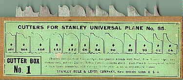
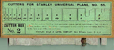
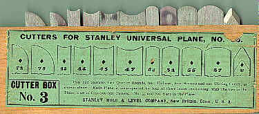
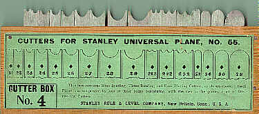
The image below shows the common packing method
Stanley used for the #55; 4
wooden boxes, with covers (not in the images) hold the
cutters. Each box has a
label to illustrate each cutter within the box. The four
boxes illustrated here
show the 52 cutters that were offered with the plane when it
made its debut. It
appears that one of the boxes was made for the Australian
market, so don't
adjust your display.
|
|
|
|
|
|
The plane came packed in many different containers.
The earliest is a
finger-jointed chestnut box with a sliding cover. After
that, Stanley shipped
the tool in a tin box that has a sliding cover. For a short
time, they shipped
it in an hinged orange painted wooden box that had supports
to hold the plane
steady (these are good boxes in areas prone to earthquakes).
Both the metal box
and the hinged wooden box were offered during the sweetheart
era. Eventually,
Stanley settled upon a stiff pasteboard box, with the
earlier ones being tall
and slender, and the later ones being more like a common
shoebox. It's not too
difficult to find this plane in its original box as many of
the craftsmen found
them convenient to hang onto them to keep the plane's parts
from entering the
dimension socks enter. It's also possible to find a good
number of the tools in
nice craftsman-made boxes. If you're dying to own one of
these beasts, it's a
better buy to get one complete and in the original box.
You'll eventually grow
to hate it, and it's easier to recoup your investment, when
you go to sell it,
with the tool complete and in its original box.
OK, that's enough now. My head hurts just thinking
about this
monstrosity....
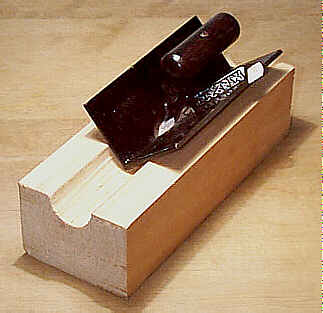
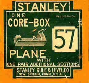
#56 Core box plane, 4"L, 3/8"W, 2lbs, 1909-1923. *
 This is one of Stanley's
scarcer planes. When most woodworkers (or anyone who thinks
they are) see this
plane, as well as the #57, they think it's for planing into corners. It
certainly could do that,
but that's not its gig in the woodworker's stand-up act.
This is one of Stanley's
scarcer planes. When most woodworkers (or anyone who thinks
they are) see this
plane, as well as the #57, they think it's for planing into corners. It
certainly could do that,
but that's not its gig in the woodworker's stand-up act.
It was used by patternmakers to plane out semicircles
9/16" to 2"
in diameter. These semicircles, or cores, need to be planed
to great accuracy
for the casting of parts that have semicircular or circular
voids in them, and you fans of Euclid know that the only
angle that can be scribed in a semi-circle is the right
angle.
The plane's sole, like a good many similar core box
planes, is machined to a
perfect right angle. On the right portion of the sole is a
shallow 'groove'
milled down at the vertex. This groove allows the cutter to
be set very shallow
in order for the plane to cut. The vertex of the sole, just
behind the cutter,
is machined to a sharp point; check for any signs of damage
there as the casting
is weakest there and can chip.
The cutter fits into a diagonal groove milled in the
left portion of the
sole; the left side of the cutter is ground so that it's
flush with the sole.
The cutter is sharpened so that it only cuts along the right
side of the sole,
which is different than how the cutter for the #57 is sharpened (see that one for
its cutter
description). The heel (top) of the cutter sticks up above
the casting, right
where it can rip unsuspecting flesh to a bloody mess, so
many of the planes
have the cutter reshaped to minimize bloodletting during
use.
The cutter is held to the main casting with a simple
slotted screw. Many
planes have screws all munged from repeated use. The main
casting 'swells' to
accept the cutter, and the early ones are embossed with the
patent date of
"PAT 3-23-09" above the slotted screw. "STANLEY" and
"No 56" are embossed on the inside of the casting.
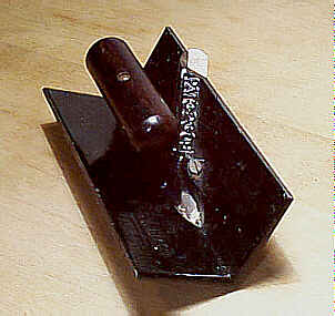 The handle is turned
from
rosewood and resembles a dowel. Some guys would reshape the
handle to make for
a better grip (the plane is an uncomfortable bugger to grip)
so make sure the
handle is 3 1/4" long and has a diameter of 1". The handle
is
positioned parallel to the tool's sole, which partially
accounts for the
uncomfortable grip. The handle is pinned, not screwed, to
the plane, on an
extension that rises from the main casting. The insides of
the main casting are
japanned black, while the outside of the casting has a
machined surface.
The handle is turned
from
rosewood and resembles a dowel. Some guys would reshape the
handle to make for
a better grip (the plane is an uncomfortable bugger to grip)
so make sure the
handle is 3 1/4" long and has a diameter of 1". The handle
is
positioned parallel to the tool's sole, which partially
accounts for the
uncomfortable grip. The handle is pinned, not screwed, to
the plane, on an
extension that rises from the main casting. The insides of
the main casting are
japanned black, while the outside of the casting has a
machined surface.
The procedure to make a core box is to layout the
diameter of the
semicircle, and then rough the waste out with gouges, a
router (non-electrical,
of course), whatever, with great care given to the area of
the endpoints of the
semicircle. Then, due to simple geometry, a perfect
semicircle is planed since a
right angle is the only angle that can be scribed in a
semicircle while
maintaining three points of contact; i.e., the sides of the
plane make contact
with the semicircle's endpoints, the sides of the core box,
and the cutter
sweeps across the arc at a constant radius.
None of these planes is 4"L. They are all 6"L. The
catalog
descriptions were either a typographical error or Stanley
was playing a joke.
It's probably the latter, if one is to judge the plane by
how well it sold;
i.e., it was one big joke. hohoho! Why Stanley felt they
needed to make this
plane, when the #57
could do all that this plane can do and more, shall
forever remain a mystery in
tooldom.
If you're not a patternmaker, and are looking for
household uses for this
tool, it makes a great bacon press for lefties and righties
both.
#57 Core box plane, 10"L, 7/8"W, 6 3/4lbs, 1896-1943. *
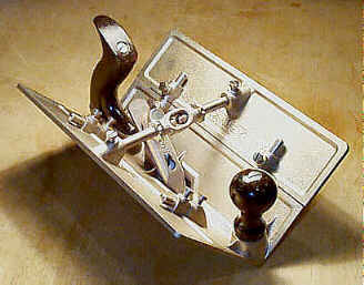 This
is another plane designed
for pattermaking use, although in the earliest literature
about the tool it
lists it as being "A tool much needed by Pattern Makers,
Wheelwrights, and
others...". Other than the hubs, which normally are cut from
the solid,
but may have been pieced together, I can't think where else
in the
wheelwright's trade a core box plane could be used. It may
have simply been
over-zealous marketing where Stanley was trying to
over-describe the uses of
the tool, not that that hasn't been done before, nor that
some today do the
same with their wares.
This
is another plane designed
for pattermaking use, although in the earliest literature
about the tool it
lists it as being "A tool much needed by Pattern Makers,
Wheelwrights, and
others...". Other than the hubs, which normally are cut from
the solid,
but may have been pieced together, I can't think where else
in the
wheelwright's trade a core box plane could be used. It may
have simply been
over-zealous marketing where Stanley was trying to
over-describe the uses of
the tool, not that that hasn't been done before, nor that
some today do the
same with their wares.
It is larger than #56 and thus can cut larger semicircles - up to 2
1/2" in diameter.
The earlier models can be found with the March 10, 1896
patent date embossed in
the main casting of the tool. The V-shaped cutter is
manually adjustable; i.e.,
there is no mechanical cutter adjustment like that used on
the common bench
planes, probably because patternmakers have a finer touch
than the ham-fisted
(by comparison) carpenters do. And while on the subject of
the cutter, this
plane's cutter is sharpened with two bevels so that they
form a V at the leading
edge. This allows the cutter to cut on the left side of
the sole and/or the
right side of the sole. The left side of the sole has the
shallow groove milled
along the vertex, which is opposite how the #56's sole is milled.
The plane, like many of the products Stanley made
during the era, is nickel
plated. And very much so, at that, as it seems that Stanley
wanted to deplete
the free world's nickel resources, with this plane as proof.
Even the nuts used
to hold the knob and tote in place are nickel plated. The
plane is often found
with its nickel peeling or tarnished. Patternmakers also had
the nasty habit of
scratching their names, or their company's, in the
extensions almost as if to
prove that they were well schooled in their ABC's.
Identifying marks scratched
into this plane, and for that matter, all others, seriously
decreases their
value to collectors.
This plane came equipped with extensions, one for
each side of the plane,
which would then allow the plane to cut semicircles up to 5"
in diameter
(the extensions are often MIA on these planes, decreasing
significantly the
tool's value). These extensions each fit onto short metal
rods, which, in turn
fit into corresponding bosses that carry slotted screws to
hold them firmly in
place. These bosses are prone to breaking and cracking, so
check them
carefully. The slotted screws are nickel plated and have
flat heads.
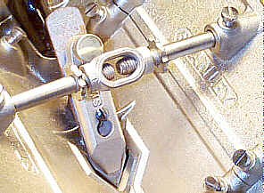 There is a cast iron
turnbuckle that keeps the extensions rigid by forcing the
extensions outward.
Flanking the turnbuckle on each side is a rod (one end of
the rod threads into
the turnbuckle with the other end unthreaded to slip into a
hollow boss in the
extension) and a lugged locking nut to keep the turnbuckle
firmly in place. The
turnbuckle is first turned to force the rods outward, and
the nuts are then
tightened, often with the end of screwdriver or similar
tool, against the
turnbuckle. One or both of these nuts is often missing or is
all munged from
repeated tightening.
There is a cast iron
turnbuckle that keeps the extensions rigid by forcing the
extensions outward.
Flanking the turnbuckle on each side is a rod (one end of
the rod threads into
the turnbuckle with the other end unthreaded to slip into a
hollow boss in the
extension) and a lugged locking nut to keep the turnbuckle
firmly in place. The
turnbuckle is first turned to force the rods outward, and
the nuts are then
tightened, often with the end of screwdriver or similar
tool, against the
turnbuckle. One or both of these nuts is often missing or is
all munged from
repeated tightening.
The turnbuckle can place a lot of pressure on the
extensions when they are
overtightened causing the extensions to crack. The
turnbuckle is often missing
on these planes, which greatly diminshes their value. Some
patternmakers would
chuck the turnbuckle, substituting it with a common round
rod.
 Additional
side
extensions could be bought - each pair increases the plane's
capacity to cut by
2 1/2". The maximum diameter semicircle that can be cut by
the plane is
10". In total, counting the 1 pair supplied with the basic
plane, there
are 3 pair of side extensions that can fit this plane. Each
has a turnbuckle
mechanism to secure them. When all the extensions and
turnbuckles are on the
plane, it is a scary looking beast with its industrial,
Bahausian
configuration.
Additional
side
extensions could be bought - each pair increases the plane's
capacity to cut by
2 1/2". The maximum diameter semicircle that can be cut by
the plane is
10". In total, counting the 1 pair supplied with the basic
plane, there
are 3 pair of side extensions that can fit this plane. Each
has a turnbuckle
mechanism to secure them. When all the extensions and
turnbuckles are on the
plane, it is a scary looking beast with its industrial,
Bahausian
configuration.
The plane is pushed and held in the hands with a
conventional bench plane
style knob and tote. The earliest models have beech while
the later have
rosewood for their wooden parts.
Check that there is no chipping about the plane's
mouth. I've seen some examples
that have replacement lever caps taken from a #78, #180, #190, etc., that's been reground to
fit the #57.
A proper lever cap is nickel plated and has its
sides bevelled along its length and the bearing surface at
its bottom isn't
straight across but is more a cross between a U and V.
This is one tool that looks better as a bookend than
it does as a lamp,
which is about all they're worth in today's woodworking
arsenal. Don't stare at
one of these babies that are in mint condition, or you'll go
blind from all
that glaring nickel plating.
[ START ] |
[ PREV ] | [ NEXT
] | [ END ]
[ HOME
]
Copyright
(c) 1998-2012 by Patrick A. Leach. All Rights Reserved.
No part may be
reproduced by any means without the express written
permission of the author.